Available Signals Window
Available Signals:
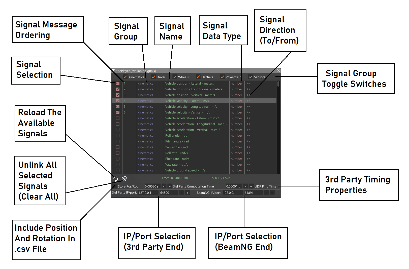
The Available Signals Window lists all the properties of a vehicle which can be included in the tightly-coupled system. These signals appear by category (which can be switched on or off using the checkboxes at the top of the window).
The six groups (categories of signal type) are as follows:
Kinematics signals include vehicle positional data along with angular and velocity/acceleration data.
Driver signals include driver-level controls such as pedals (throttle, brake) and steering. Many of these signals can be fed into BeamNG from the third party, or they can be sent to the third party.
Wheels signals include data related to the vehicle’s wheels, such as wheel speed, angular velocity and propulsion and brake torques. Many of these signals can be fed into BeamNG from the third party.
Electrics signals include selected data from the vehicle’s electric system, such as indicators, lights and battery properties. Electrics-related sensor data is available, such as oil temperature.
Powertrain signals include selected data from the vehicle’s powertrain system devices, such as output torques and gear ratios across the different components of the powertrain system.
Sensors signals include data from the supported sensors which are attached to the vehicles. Sensors can be attached using the ADAS Sensor Configuration Editor for vehicles (see the documentation for that feature, if required). Supported sensors are: IMU, GPS, Ideal RADAR, and the Roads Sensor. Other sensors contains data readings which are too large to be sent over the socket in single packets (eg LiDAR, Camera, etc) so they are not supported for co-simulation.
The user has the option of selected whether to store the vehicle pose (world-space position and rotation) in the .csv file. This is done through a checkbox near the bottom of the window.
The user should use the Available Signals Window to build two messages. Signals are added to the message by ticking the box to the left of the property in the list. The direction arrow towards the right of list will determine the direction of travel for the signal (’to’ or ‘from’ BeamNG with respect to the third party).
The second column shows the position (in each message) of each signal (property). As the user selects/removes signals, this will change as appropriate. This order is the same order which will appear in the .csv file.
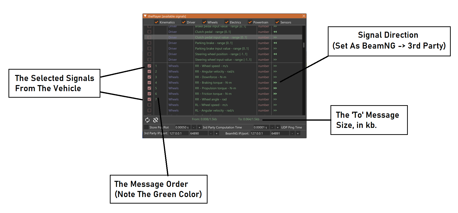
‘To’ Message:
The ‘To’ message is an ordered collection of values which are sent from BeamNG to the third party (eg Simulink). The order is defined by the order in which the signals appear in the .csv file. In every time step of the coupling, a message of this format is sent (from BeamNG.tech to the third party) which contains the latest values relating to each of the signals in the message.
The message itself is prefixed by a unique Id number, which is constantly incremented with every new message which is sent. Every signal value in the message is double-valued (Eight bytes width) - even those whose type are marked as ‘boolean’ - the conversion to Boolean is/should be handled by the third party software.
To include values in the ’to’ message, the direction button should be pointing rightwards.
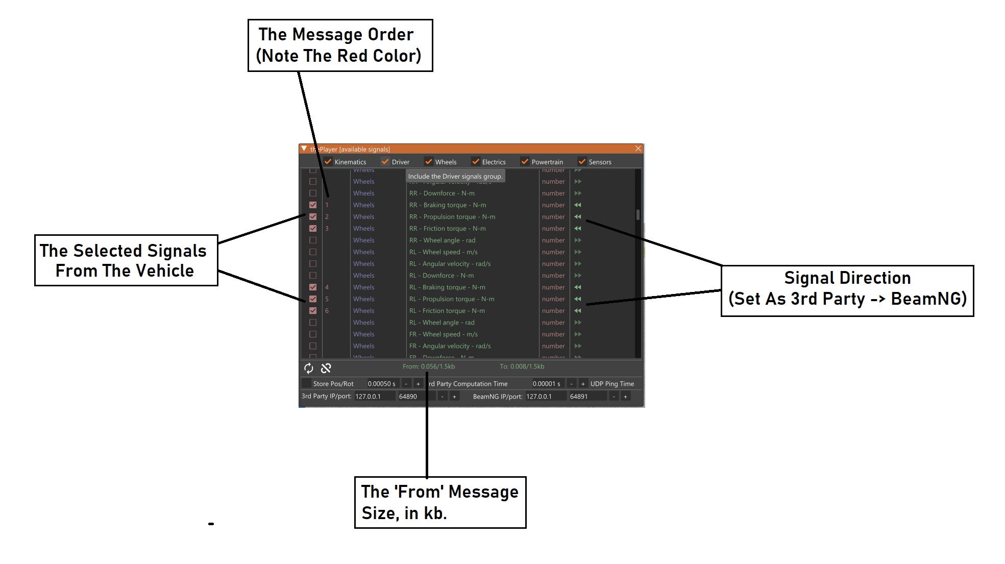
‘From’ Message:
The ‘From’ message is an ordered collection of values which are sent from the third party (eg Simulink) to BeamNG. Again, the order is defined by the order in which the signals appear in the .csv file.
Message Sizes:
The Available Signals Window displays the size of each of the two messages, as they are being built. This is shown near the bottom of the window.
The coupling works by using UDP to send the messages from BeamNG -> third party and third party -> BeamNG. The messages should be limited to a size of 1.5kB (1 MTU), since if larger messages are used, the message packets may be split. We wish to avoid this. If the message is larger than this limit, the Available Signals Window will show a warning. The user should be aware of this consideration when creating .csv files.
Coupling Timing Values:
There are two timing properties which the user should set in the Available Signals Window:
The 3rd Party Computation Time is the time which the third party is expected to take, to compute one step of simulation. This should be known by the user, perhaps by measuring it. The value should be set in this window, then when the .csv file is generated, this information will be included. It is important to get this value as accurate as possible, so that the coupling algorithm can determining the best window width which to use - this will make the coupling as efficient as possible.
Note: if the computation time is not uniform (ie it varies from time step to time step), the maximum should be sufficient. There will be a loss in coupling efficiency in this case.
The UDP Ping Time is the ping time of the UDP connection. This can be determined from the command prompt (a quick internet search will show how to do this). If BeamNG and the third party are running on the same machine and the loopback port (127.0.0.1) is used, the UDP Ping Time will be very fast. In this case, the default (or another very small number) should be sufficient.
Coupling Sockets/Ports:
The .csv also contains the socket and port identifiers for both sides of the coupling. The user should also ensure these are correct when generating the file, since both BeamNG and the third party will check the file and expect information on the given socket/ports.