Introduction
The Co-Simulation Editor allows the BeamNG.tech user to set up a tightly-coupled system between a BeamNG vehicle and third-party software (such as Mathworks Simulink). A GUI-based tool faciliates the creation of .csv files which are used as a contract to describe the parameters of the message-passing between the two sides of the coupling. The user can use the mouse to choose from a multitude of properties across the vehicle (kinematic properties, wheel data, vehicle electrics data, powertrain data, etc) - properties which are to be sent to the third party. Incoming properties (from the third party) are also selected in a similar way.
Both sides of the coupled system read the .csv file which is generated with the GUI, then a button is used to start executing the coupling between the two. The execution of the coupling can then later be stopped from the same button.
The CSV File:
The .csv file generated by the Co-Simulation Editor can be thought of as a contract between both sides of the coupling. It defines the connection data so both sides know where to send messages and where to receive them, and contains ordered lists of signals which will send data messages from each side to the other. It also contains some other pertinent details such as the vehicle.
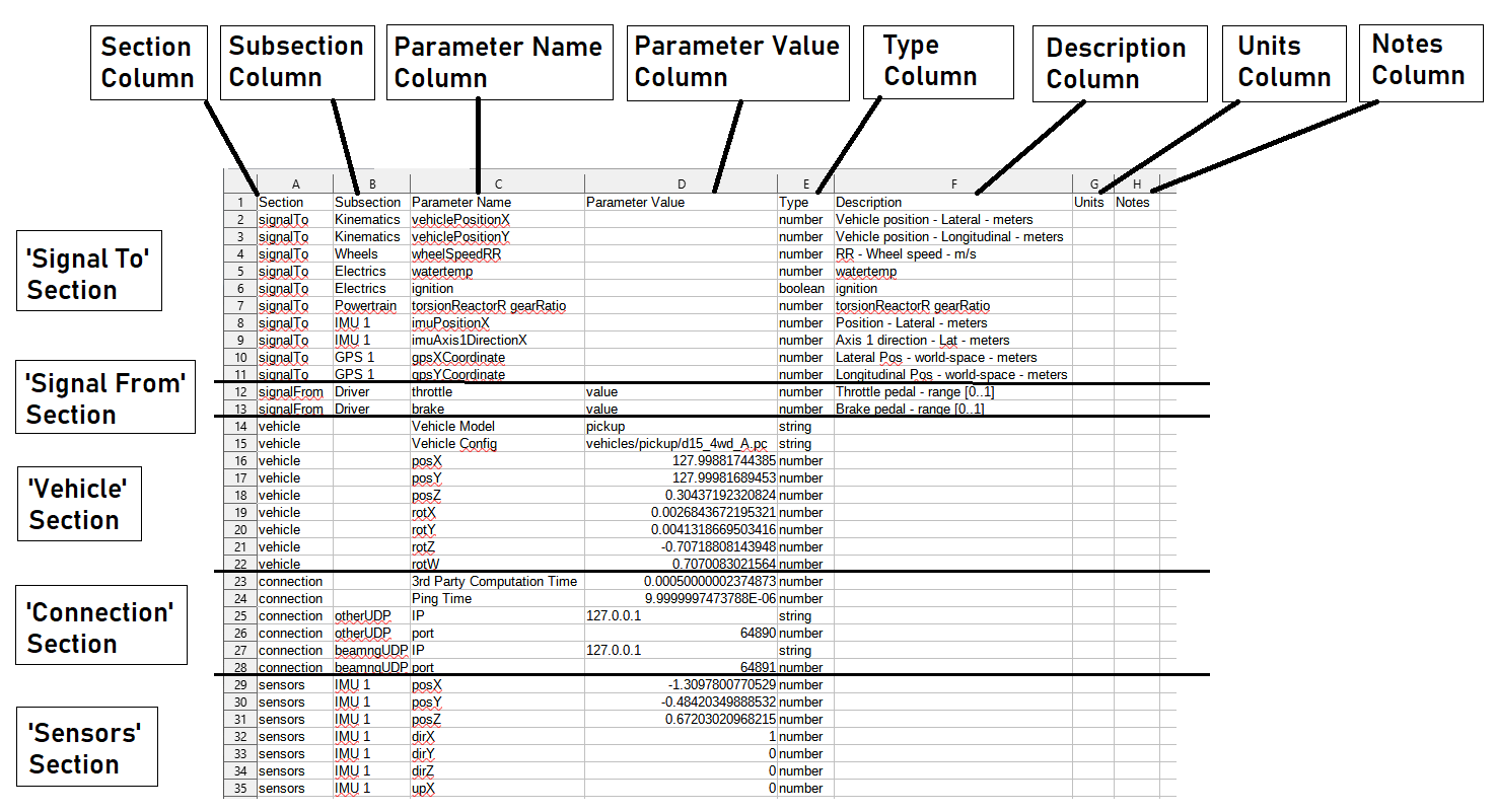
The file contains eight columns, and is divided into five sections. An example .csv file is illustrated below.
Sections:
The sections of the .csv file can be described as follows:
The signalTo section contains an ordered sequence of signals (properties) which will be sent from BeamNG to the third party, as a message, in every time step of the coupling. This message is discussed in more detail, later in the documentation.
The signalFrom section contains an ordered sequence of signals which will be sent from the third party to BeamNG, as a message, in every time step of the coupling. This message is discussed in more detail, later in the documentation.
The vehicle section contains some basic information about the vehicle associated to the coupling. Coupling should be executed on the same vehicle with which the .csv file was created for, since the available signals can be different for different vehicles. However, this is not strictly enforced and it is possible to run using a .csv file which was generated for a different car. The user should take this into consideration. It could potentially work fine for different models of the same vehicle.
The connection section contains socket and port information for each side of the coupling, and some fixed expected computation timings.
The sensors sections contains sensor parameters for all the sensors which were attached to the vehicle at the time of creating the .csv. This is done so that the sensors can be re-created if they do not exist upon executing the coupling.
Columns:
The columns of the .csv file can described as follows:
The Section column defines which of the five sections the row relates to (it will be one of: signalTo, signalFrom, vehicle, connection, or sensors).
The Subsection column depends on the section. For the signals sections (to and from), it provides the signal group (eg Kinematics, Driver, Wheels, etc). For the IP and port values in the connection section, it provides which end the IP/port relates to (it will be either: otherUDP or beamngUDP). For the sensors section, it will provide the sensor type and Id number (eg IMU1, IMU2, GPS1, GPS2, etc). For other sections, the Subsection field is not used.
The Parameter Name column also depends on the section. For the signals sections (to and from), it provides the signal name as it appears in code (eg vehiclePositionX, watertemp, ignition, etc). For the vehicle section, it provides the field (Vehicle Model, Vehicle Config, or position/rotation dimensions). For the connection section, it provides the field (3rd Party Computation Time, Ping Time, IP, or Port). For the sensor section, it provides the sensor parameter (positions/directions are split into dimension components).
Note: the vehicle rotation (if stored in the .csv file) is in the form of a unit quaternion (it has x, y, z, and w components). This may be unfamiliar to some users. It is written by the GUI however, and does not require modification. If the user does decide to modify this, they should understand quaternion mathematics or may find the vehicle appearing in unusual rotational poses.
The Parameter Value column is unused for the ‘signals to’ section. The vehicle section uses this column to store the values for vehicle data, IP, and position/rotation. The connection section stores the timing values and IP/port numbers. The sensors section stores the value of the row-associated sensor parameter (given in the parameter name column).
Note: The ‘signals from’ section uses this column to store the channel (either value, multiply, add, or freeze), however this functionality is not currently used with the tool - all ‘from’ signals will replace the BeamNG.tech target.
The Type column provides the data type of the row-associated parameter value. This will either be string, number, or boolean. Note that the signals (to and from) will only contain number or boolean (there are no strings passed in these sections).
The Description column provides a stored description for each signal (stored internally). It is not used for the other sections of the .csv file.
The Units column is currently not used. The user may feel free to add their own units here, if preferred.
The Notes column is left for the user to add their own notes in each row, if preferred.