Road nodes can be moved individually with either the translation gimbal (which appears at the node when it is selected either by clicking on the node or from the listbox in the Road Edit Window), or by dragging the node with the mouse.
Some features which work on multiple roads (together) can be found directly on the Main Tool Window, but for individual road editing, the Road Edit Window contains a multitude of features. Individual node editing can also be performed (eg height/lateral rotation), but will be discussed separately in a later section.
Main Tool Window Features:
Bulldoze:
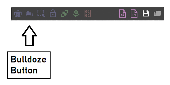
Using the mouse, this feature allows the user to draw a polygon on the map to encircle roads which should be deleted. The user can double-click the left mouse button to complete the polygon and any roads exclusively inside this region will be removed. Any linking roads (connected to roads being deleted) will also be removed. This feature is useful for quick removal of large sections of the road network or full junctions etc.
Multi-Select:
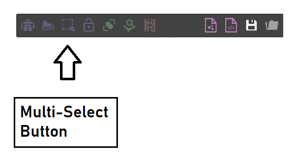
Also using the mouse to draw a polygon, the user can select multiple nodes across multiple roads and move them together with the gimbal. This feature is useful for placing larger structures or for road sections which should be moved together. When the editor is using this mode, other nodes/roads cannot be selected. To exit from this mode, the user can uncheck the same button on the Main Tool Window.
Road Edit Window Features:
For more intricate editing, the Road Edit Window contains various buttons to perform different functions on individual roads. These are listed below.
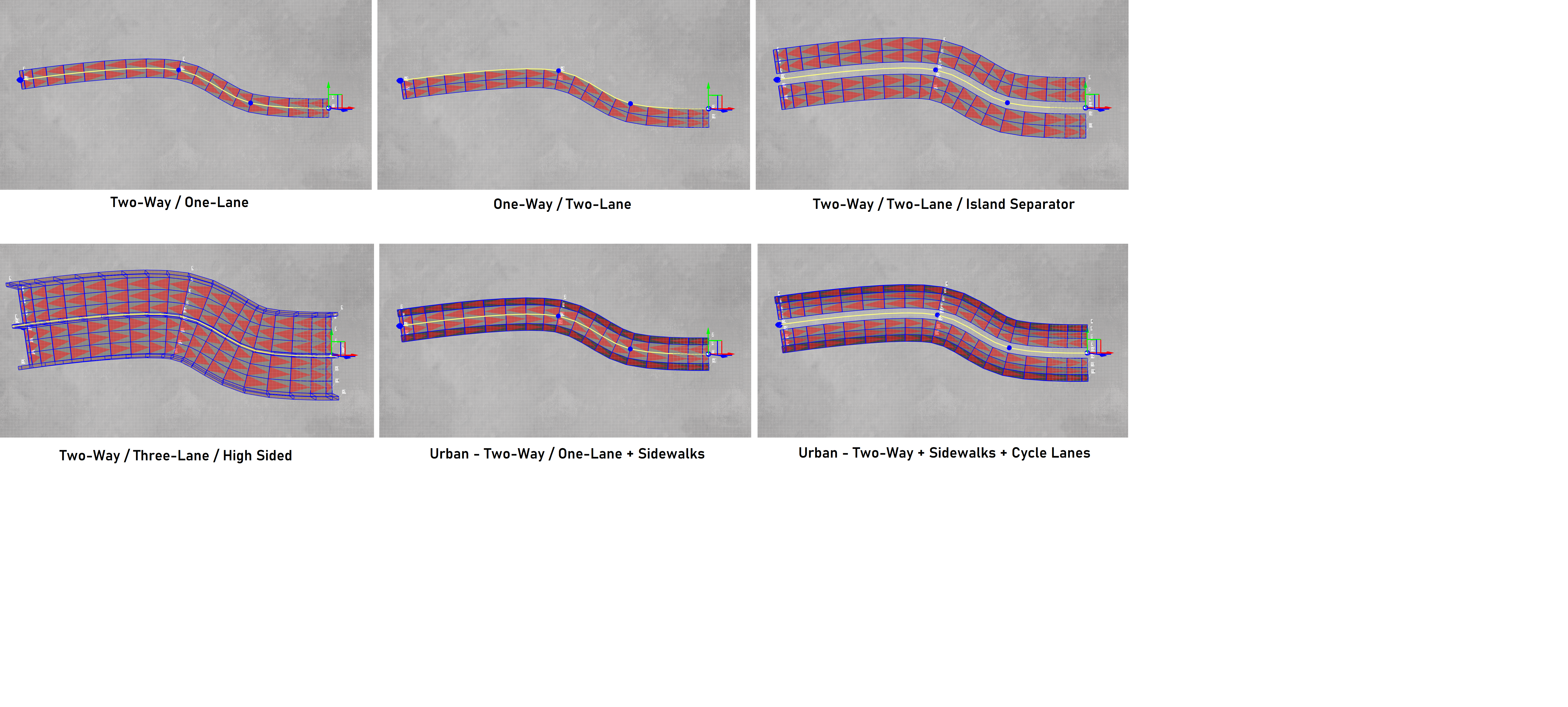
Change Profile:
Allows the user to select a different lateral road profile for the road. For more information, please refer to the section relating to lateral road profiles which appears earlier in the documentation.
Changing the profile will update the road such that it takes on the new profile. The user should be aware that upon doing so, any width or relative height offset values which may have been set at each node on the road, will be deleted. Each node will adopt the values stored with the new profile.
Switching between different profiles is illustrated in the image below:
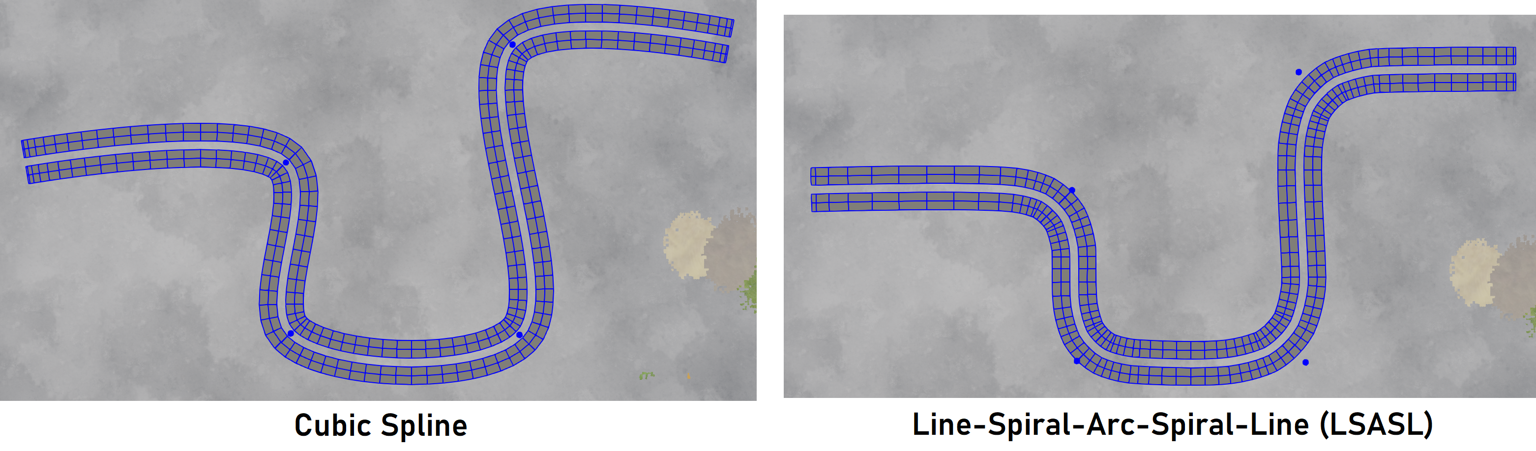
Toggle Spline Type:
Changes the type of spline used for the road (spline or LSASL types). This will be discussed later in the documentation.
Split Road:
The road will be split into two separate roads at the selected node position. At the split point, the two ends will be repelled slightly to make the split clear to the user. The image below highlights the process:
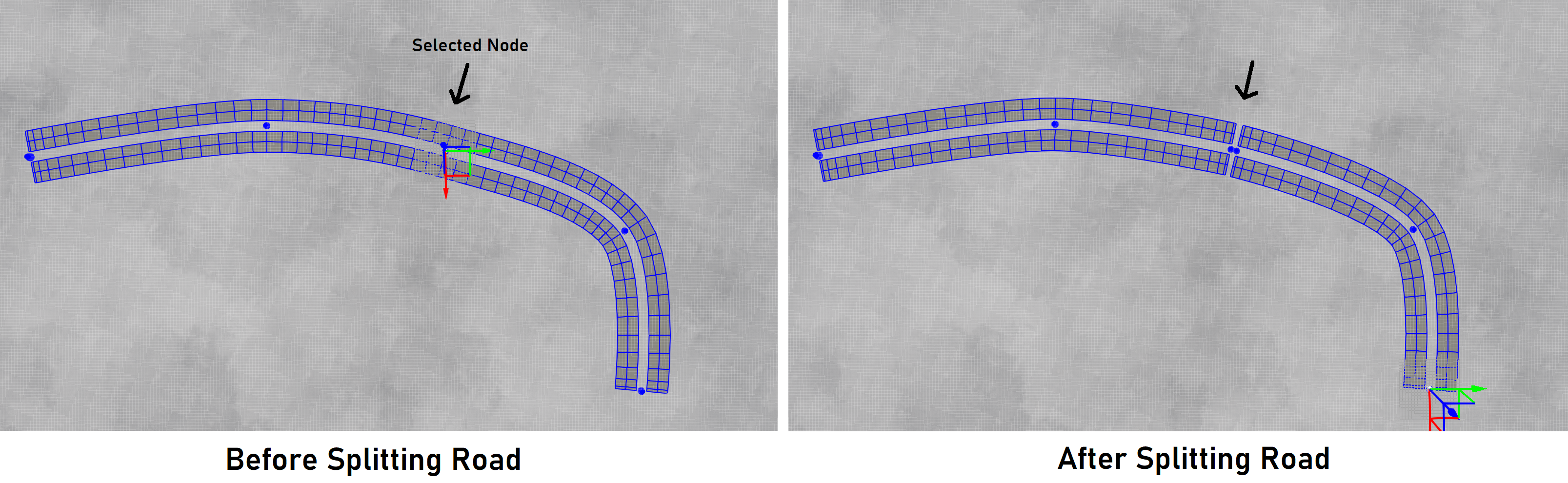
Note: only roads which are not linked to other roads can be split - the button will only appear for those roads.
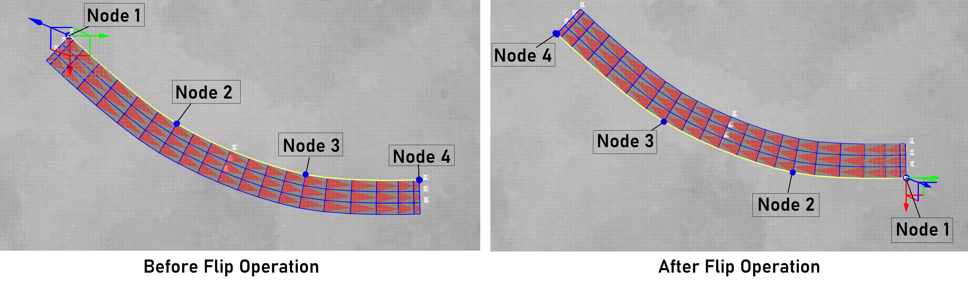
Flip Road Direction:
This feature flips the node order of the road. The start becomes the end, and the end becomes the start. This is sometimes useful, especially for one-way roads, where it will flip the direction of travel of the road.
The following image illustrates the result when acting upon a three-lane one-way road:
Locking:
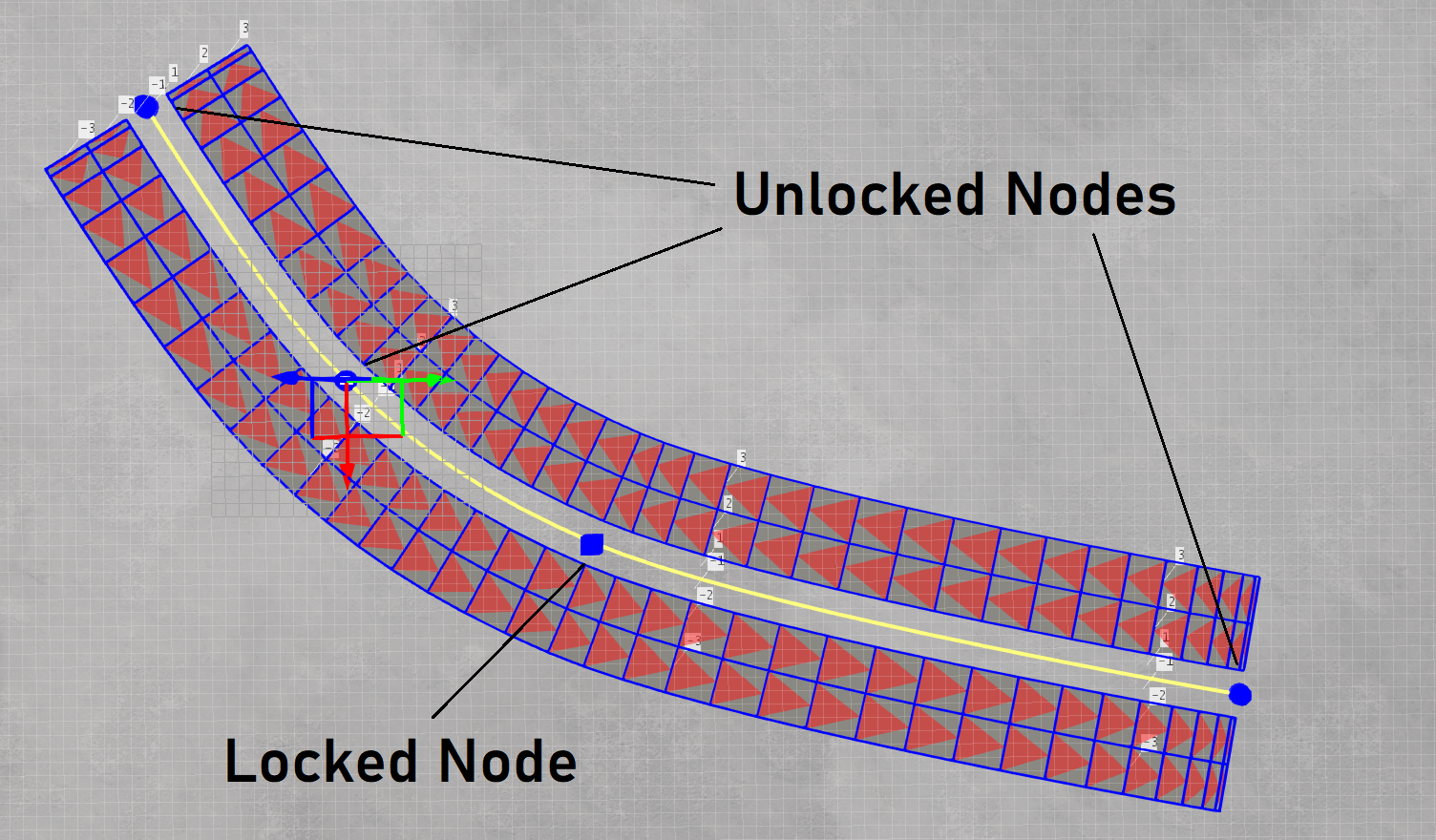
Individual road nodes can be ’locked’ such that they cannot then be moved with the mouse. The node sphere will change from the usual sphere to a cuboid shape to indicate that the node has been locked, and a lock icon will appear beside the node.
The node can be unlocked by either clicking on the lock icon beside the node or by clicking again on the lock button. Node locking is useful if a section of the road has been created which the user wants to protect from being altered later when performing further edits, which can often happen accidentally. In this sense, the locking functionality can be thought of as a barrier to prevent erroneous changes later.
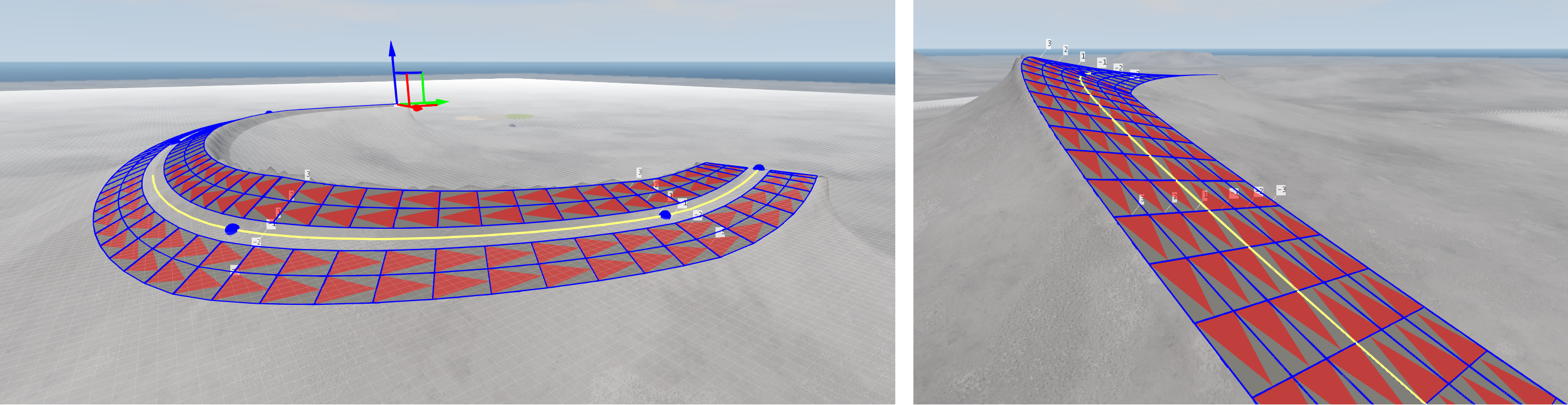
Conform Road To Terrain (Toggle):
This feature will force the road to ‘snap’ to the terrain height (the height map) and remain so after any future edits to the road (until this feature is switched off). The image below highlights the difference; the left image shows a road which is not conformed to the terrain - parts of the road appear to pass underneath the height map, and the right image shows the road after conformation to the terrain.
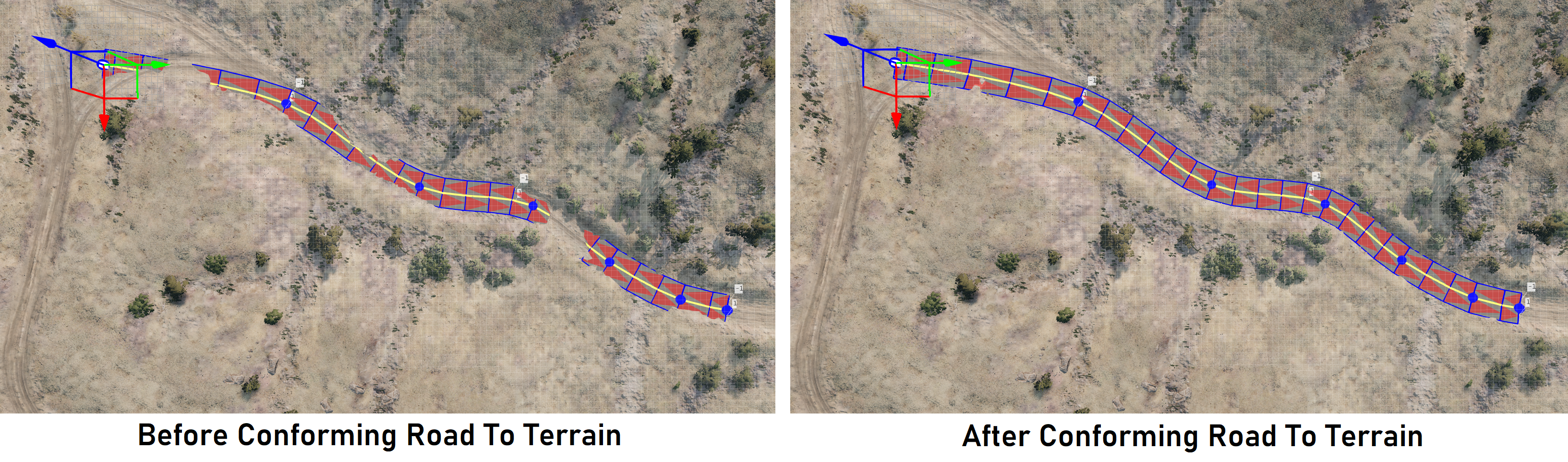 Conforming A Road To The Terrain
Depending on how noisy the terrain underneath the road is, the road may appear to have artefacts and/or become undriveable. The user should be careful when using this feature. If terrains do not fit well with the road, terraforming may help to improve the situation - this will be discussed later in the documentation.
Conform Terrain To Road:
Instead of snapping the road to the terrain, the terrain can be snapped to the road through a terraforming operation.
This feature can be used to create hills and valleys on the map, and prevents roads from appearing to float in the sky, which may be unwanted behaviour unless the road represents a bridge. Terraforming will be discussed separately in this documentation, in its own section.
Note: the user should be careful when terraforming individual roads where there are other roads which cross over/interact with it. The terraforming operation will only consider the selected road - it has no information about neighbouring roads. For this reason, the process could result in unexpected behaviour.
Note: Any terraforming operation which has had unintended consequences can be undone using the undo (CTRL+Z) feature.
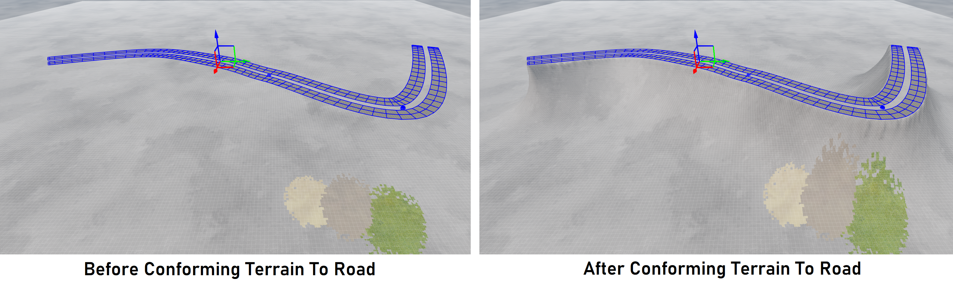 Conforming The Terrain To A Road
Using the corresponding ‘domain of influence’ slider, the amount of terraforming can be controlled. This will be discussed below.
Resolution Sliders:
The Road Edit Window contains (up to) two sliders to control the longitudinal resolution of the road. These are the ‘Linear Resolution Slider’ and ‘Arc Resolution Slider’.
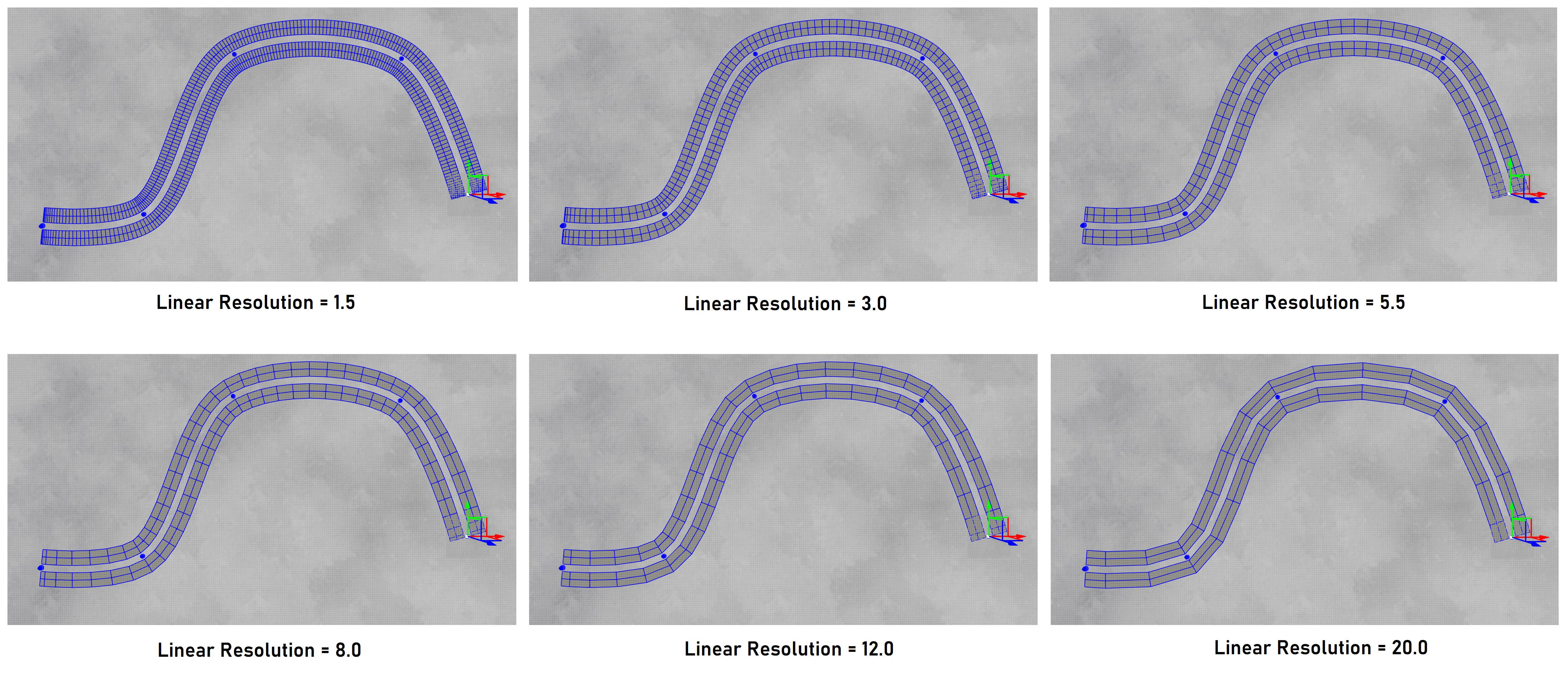
The Linear Resolution controls the general resolution of the road, longitudinally - it does not affect circular arc sections. The series of images below show how the Linear Resolution Slider acts upon a typical Spline Road.
The Arc Resolution controls the longitudinal resolution of circular arc sections only, which appear in LSASL splines and in Arc Roads. The series of images below show the Arc Resolution Slider acts upon a typical Arc Road.
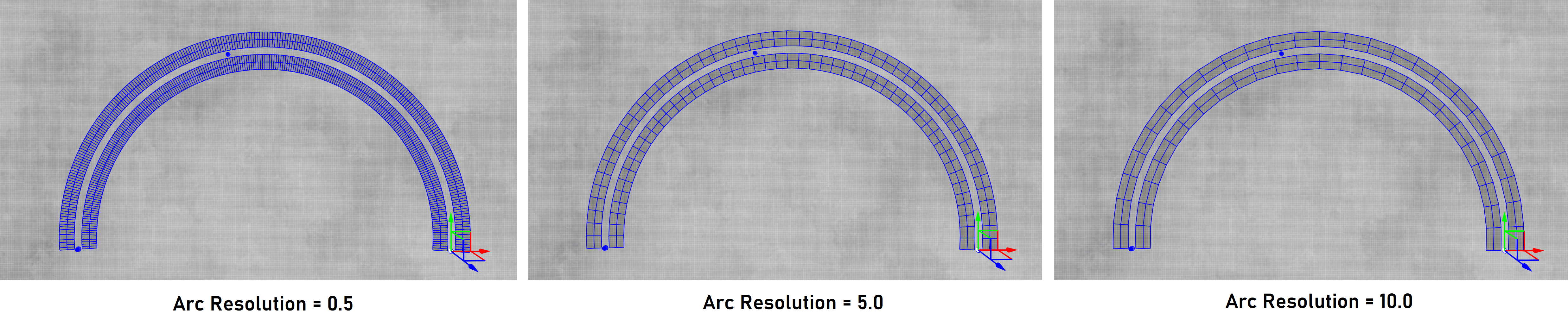
When setting the resolutions, there is a trade off; smaller resolutions represent curvature better, creating smoother-looking roads, but this comes at the cost of using many more triangles which make the road more computationally expensive. We recommend the user only reduces the resolution sliders when absolutely necessary, such as at very tight bends which look unnatural due to being linear when they should be curved. It is left to the user to take care with this feature.
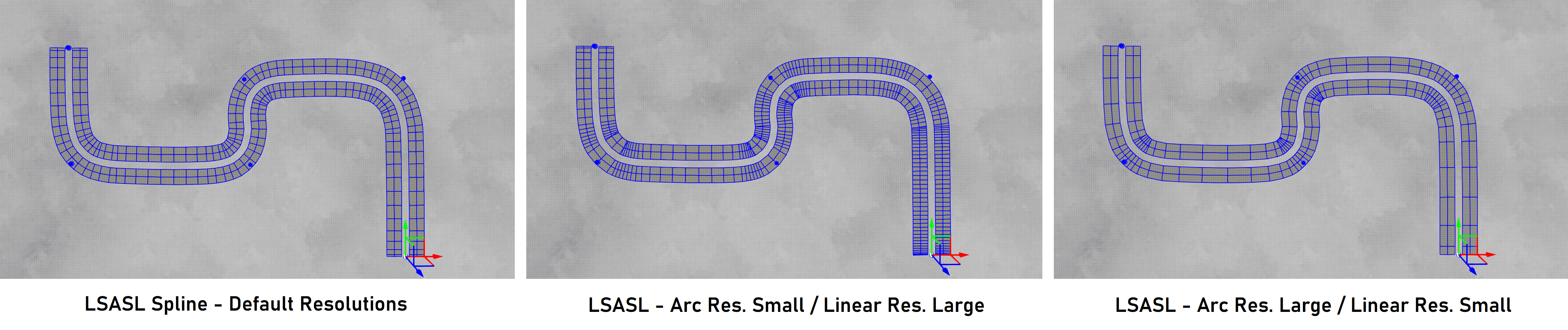
The only type of road for which both sliders appear are the LSASL (Line-Spiral-Arc-Spiral-Line) splines. In this case, the user can experiment to find the best values for the sliders. Some typical value pairs are shown in the images below. We recommend the defaults to be used unless this strongly hinders practicality.
Movement Field Slider:
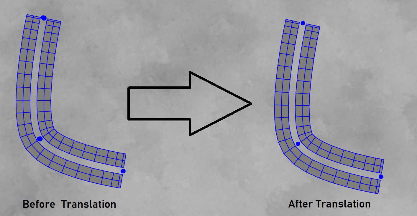
There are two ways to translate (move) roads on the map; by moving individual nodes or by moving roads rigidly. The ‘Movement Field Slider’ relates to the former.
This slider allows the user to interpolate between these two modes to allow a translation on the road which is a mixture of the two; the size of the field describes how far away from the mouse there will be movement, so larger values tend towards a rigid translation while smaller values tend towards the moving of a single node. This feature can be used to translate the road in a manner similar to an elastic band, keeping some of the local structure of the road, whilst neglecting the global structure. The user can experiment and see which values are prefered.
The images below show different-sized movement fields:
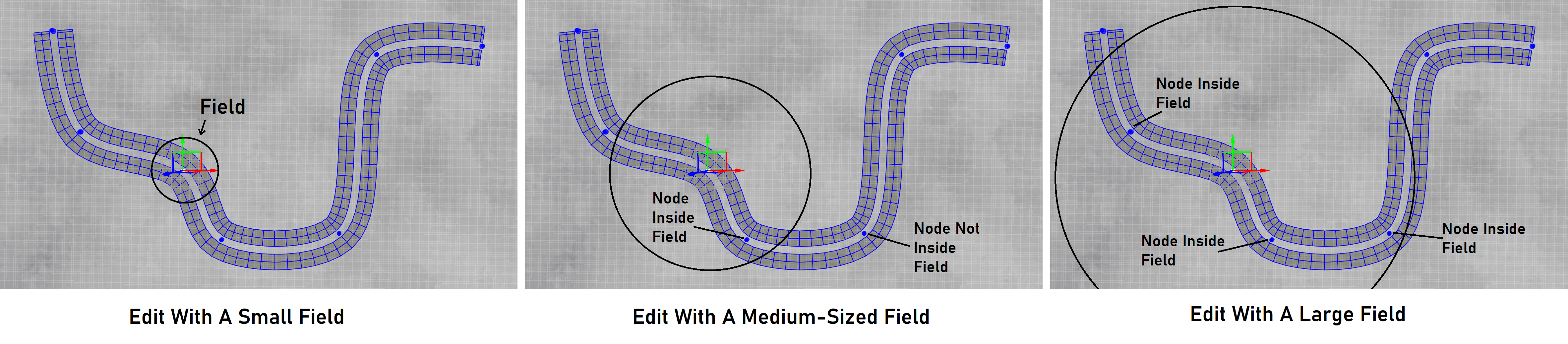
The left-most image shows a small field, where if the user was to move the selected node, no other nodes would move since they are not within the domain of the field (the circle). This is the the default behaviour, where the movement field is set to a small value. Only one node (the selected node) moves upon translating.
The center image shows a medium-sized field which is large enough to encompass one of the neighbouring nodes. This time, if the user moves the selected node (the node which has the gimbal upon it), then this neighbouring node will also move since it is within the domain of the movement field. It will not move as much since the amount of movement is dependant upon distance to the center of the field (which is the selected node).
The right-most image shows an even larger field. This time, the field encompasses three neighbouring nodes. If the user translates the selected node using this field, all of those neighbours will also move.
Rigid Translation Button:
Roads move in a rigid manner when all nodes move at once by the same amount, thus keeping the road rigid and preserving its global shape.
If a definite rigid translation of the road is required, this toggle button should be pressed. Doing so will hide the Movement Field Slider. With rigid translation, moving any node will move the whole road as one part (as if it was completely rigid). This is especially useful if the user wants to raise the height of the whole road by some fixed amount, rather than moving all nodes separately (which would be time consuming).
Domain Of Influence:
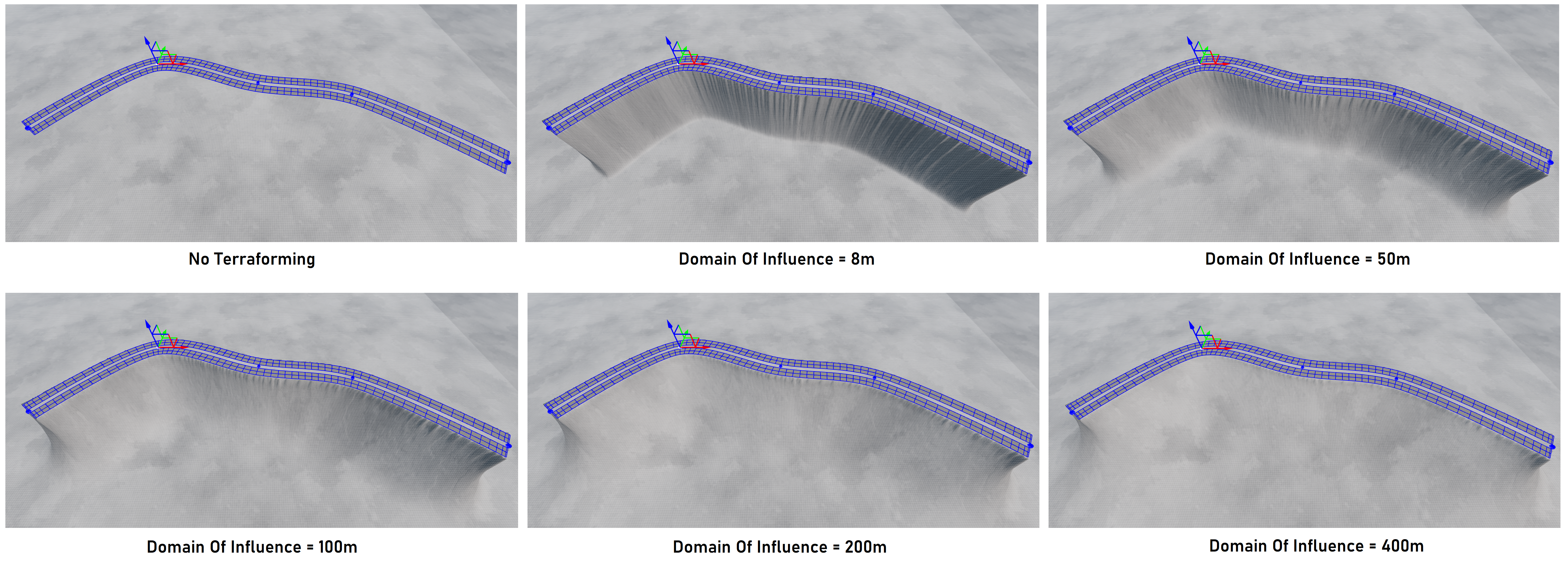
The Domain Of Influence Slider is used when terraforming (conforming the terrain to a road). It describes the distance, in meters, from the road at which changes should take place to the terrain. The effect is reduced the further away a position is from the road, but the slope of that effect is controlled with the Domain Of Influence Slider.
The series of images below illustrate the effect that different positions of the Domain Of Influence Slider will have on the terrain, for the shown road. The road was created in the usual way, then elevated above the terrain. The top-left image shows the road without any terraforming. The rest of the images show the progressive effect as the slider is moved from left to right.
This is noted above, where the slider is used when conforming the terrain to the road. Terraforming will be discussed in greater detail later in the documentation, where it has its own section.
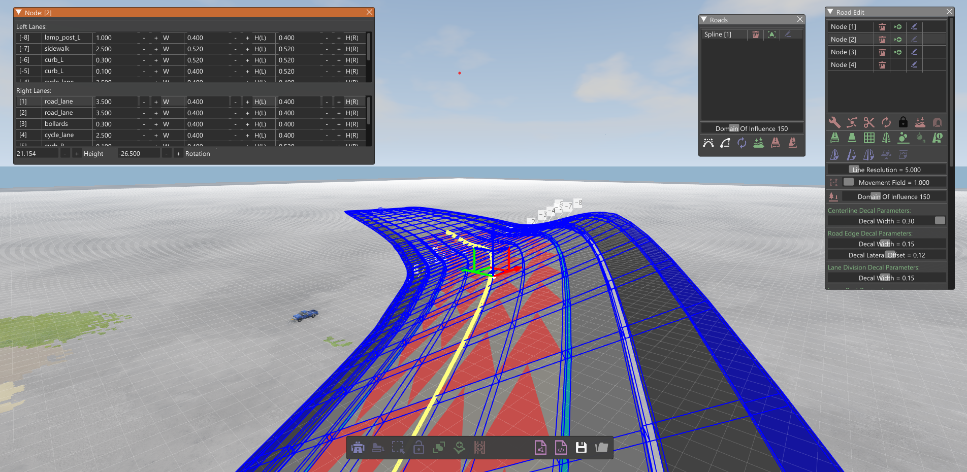
Node Edit Window Features:
At the node level, there are further editing features which cannot be found in the Road Edit Window.
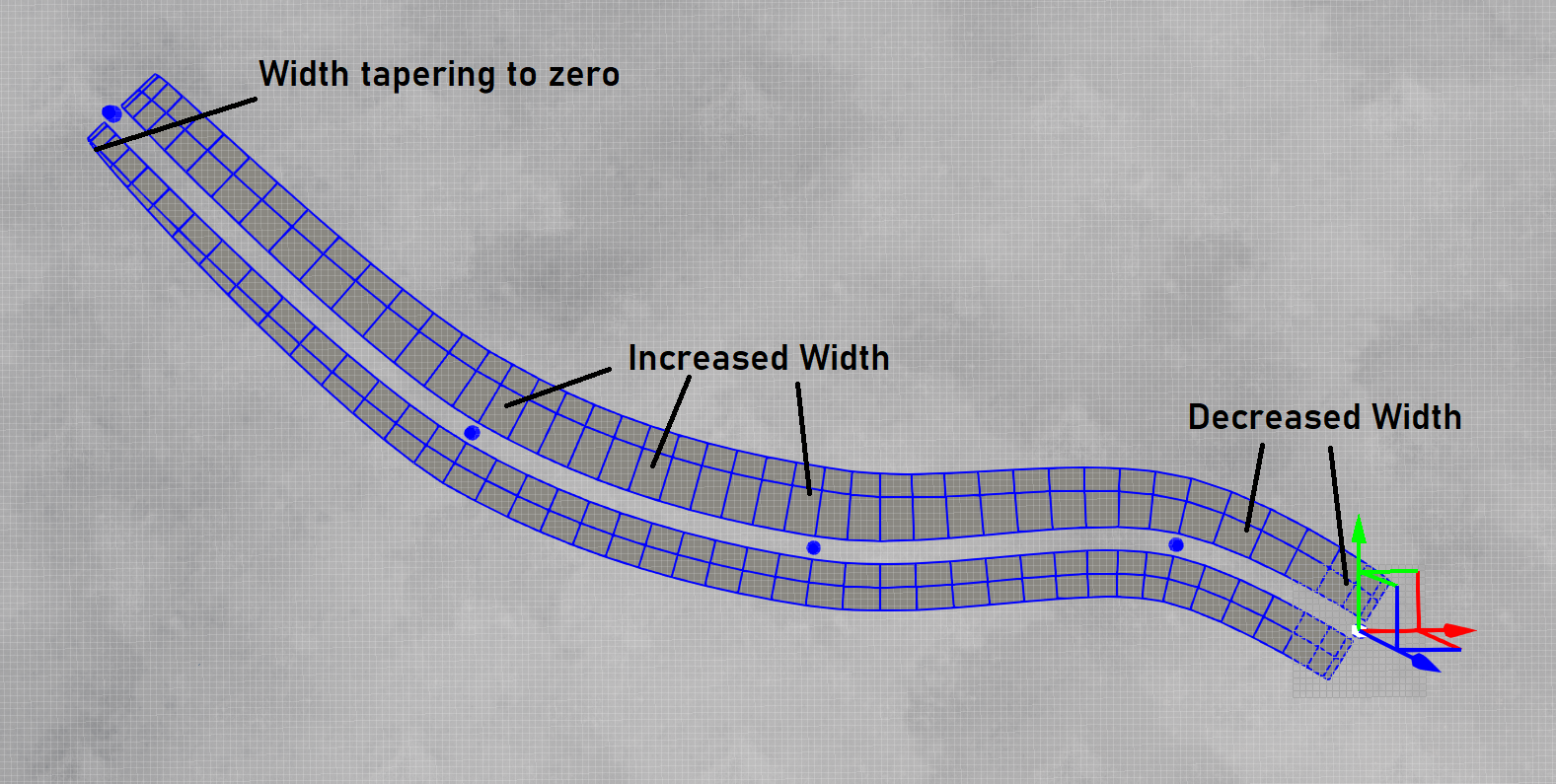
For each lane in the road profile, the lane width and relative height values can be edited (at the selected node). This is done in a way similar to how it is done in the Profile Edit Window. When changes are made here, though, it only affects the selected node. Widths and relative heights are linearly-interpolated across the node (from the previous node through to the next node). This allows the user to taper and widen lanes as required.
The image below highlights how the lane widths can be changed at the node level.
The image below shows how the relative heights of lanes can be changed at the node level, to create smoothly-changing cambers longtiduinally across the road. Relative lane heights can be set in the range [0.0m, 3.0m] and there are separate fields for the inner and outer height to allow slopes to be created.
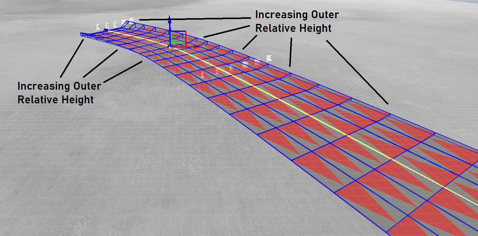 Changing Relative Lane Heights
Lanes can also be collapsed by setting the width value to 0 meters. This will taper the road to zero (also shown in above image). If this is done at the start or end node of the road, then the collapsed lane will not be selectable when linking the road to another road. This is desired behaviour since it allows the user to end lanes whilst still maintaining good continuinity with the successor road. The user should experiment with this feature to see how it will work in practice with their road - if too much width changes are made, the linking tangents can be severely altered, creating road joins which may appear unrealistic. We recommend minimising large width changes near the start/end of roads which are to be joined to other roads.
At the bottom of the Node Edit Window, the node height can be set directly. This has the same effect as translating the node using only the Z-Axis of the gimbal.
The lateral rotation (in degrees) can also be set here. This is the rotation around the forward direction of the road at the selected node, and we allow the user to select angles in the range [-50.0 deg, 50.0 deg]. This should be more than sufficient for any realistic road banking, and can be combined with terraforming operations to create banked terrains which conform to the road.
Some examples of roads with edited lateral rotations are shown in the following illustration.