Lateral Road Profiles:
Each road in the editor contains a corresponding lateral ‘profile’ which describes the cross-sectional properties of the road. This contains information for each lane in the road (including how many lanes there are). The default lane widths and default relative height values can be set on this profile, so that when the user creates the road (eg after adding nodes with the mouse), these properties appear on the road. Later editing can be made to the relative widths and heights at each node, as required.
Note: There can only be one lateral profile per road. However, roads can be split or lanes can be collapsed to aid the user who wishes to create roads with different longitudinal sections.
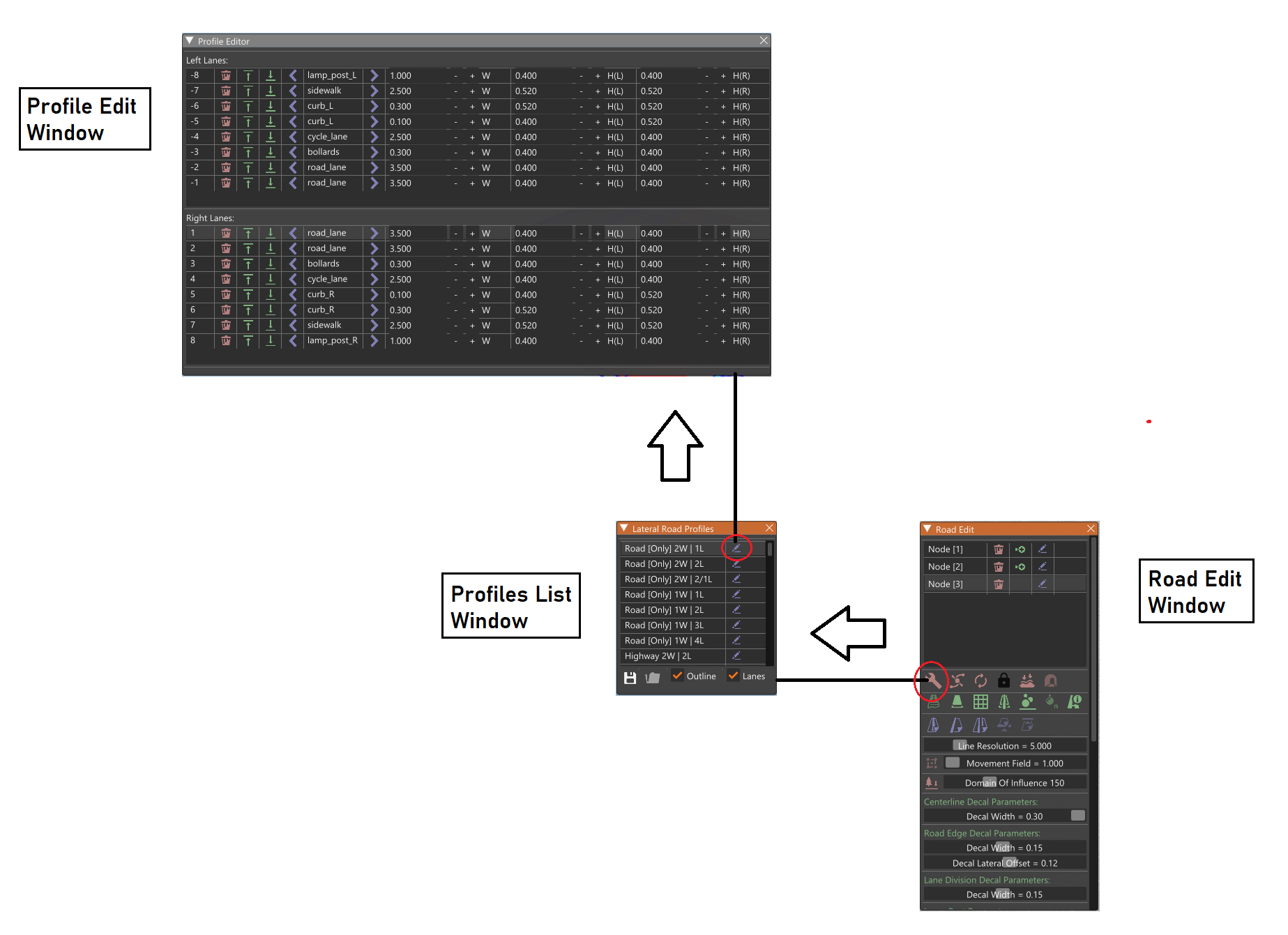
The default profile (when creating a new, first road) is a bi-directional road with one lane on each side. In order to change the profile (either before the road is drawn or afterwards), the user can click on the Profile Editor icon on the Road Edit Window.
 Window Sequence For Profile Editing
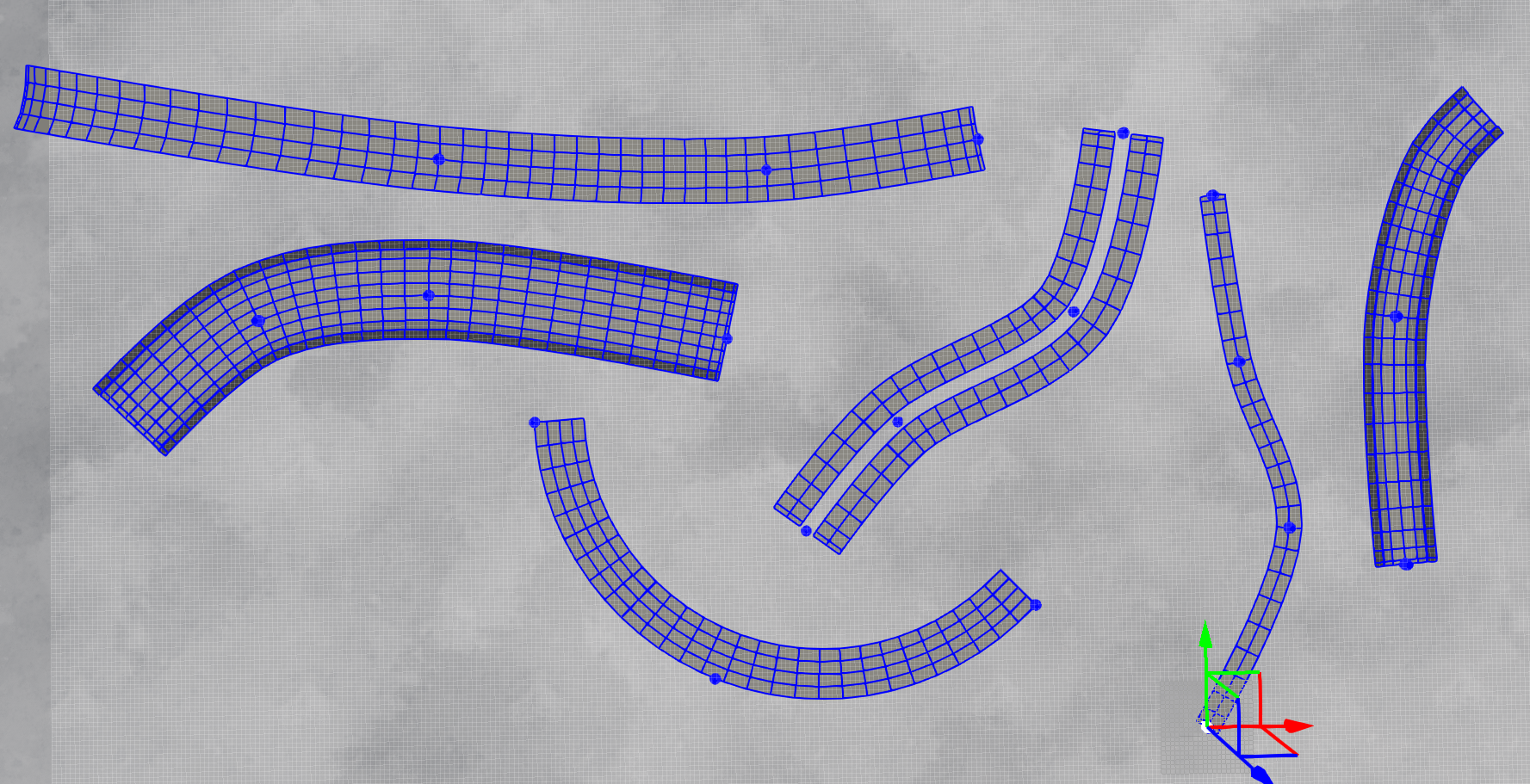
The Lateral Road Profiles Window then appears and the editor camera is moved to an auditioning pose; a small segment of the selected road profile is displayed at altitude, and the camera slowly rotates around it. The automatic rotation should provide an idea about how the road will look from various angles.
The user can then choose from a list of template profiles in the Lateral Road Profiles Window. A wide selection of standard profiles can be found in the list, comprising both bi-directional and one-way roads. Some profiles are wider and more suitable for usage in highways/motorways, and some are suited more for urban locations - these contain designated lanes for road islands, sidewalks, cycle lanes etc (more on this below). At the bottom of the list, there are various empty ‘user’ profiles which can be customised as required - here there are sets for both bi-directional (two-way) and one-way road types.
Visualisation Components:
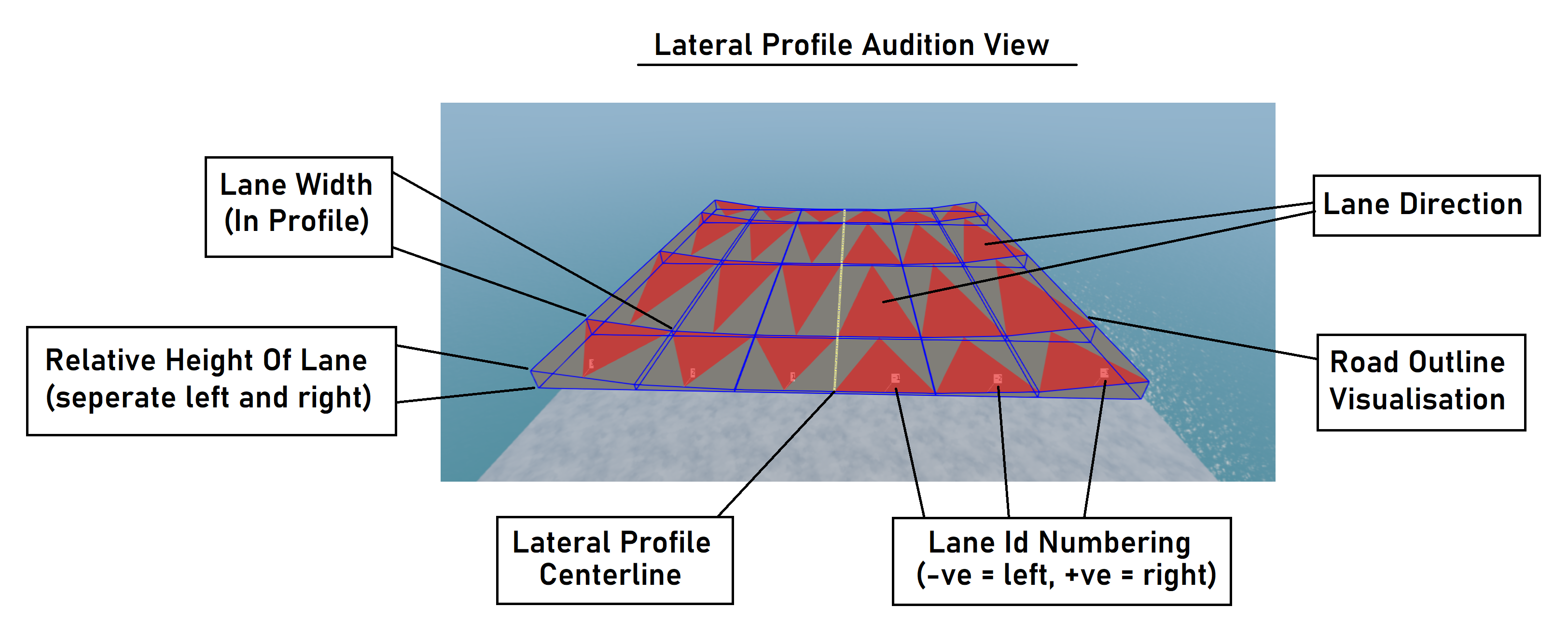
In the lateral profile audition view, the user can choose which information to render on the example road (road outline markings, road lane information). The following image shows a lateral road profile in the lateral profile audition view.
The visualisation details are described below:
The Road Surface is shown as connected grey quadrilateral panels.
The Road Outline is shown as a quadrilateral mesh of thin blue lines, helping to highlight each section of the road.
The Road Reference Line is shown as a yellow line (note that this line may not actually be in the lateral center of the road - it will appear at the division point between the left and right sides of the road).
The Lane Directions are shown as red triangles in each section of the road. These indicate the direction of travel for that specific lane, as it is in the current profile.
The Lane Numbering is shown as text markups. The road’s lanes are numbered from the road reference line: Left lanes (backwards) are negative and follow the order { -1, -2, -3, …} while right lanes (forward) are positive and follow the order { 1, 2, 3, … } from inner to outer respectively.
These visualisations are also present for roads on the map itself. They can be switched on/off (per component) in the editor’s Road Edit Window.
Note: The visualisations are only displayed if the road is sufficiently close to the camera. If the camera is distant from the road, only an basic outline shall be shown. This is to make the rendering more efficient. As the camera is moved away from a road, detailed parts of the visualisations (lane information, reference lines and markups) will progressively disappear.
Note: All roads in the editor follow the Right-Hand Traffic (RHT) format. The editor does not currently support Left-Hand-Traffic roads (eg UK, Cyprus, Australia, etc).
Profile Editing:
In the Lateral Road Profiles Window listbox, each profile contains a button beside the name which will open the Profile Edit Window. From here, the user can edit the number of lanes and set the widths and relative height offsets for each lane. Applying a change in the window will alter the example road (in the audition view) in real time, allowing the user to immediately see the changes which are made.
The Profile Edit Window contains two lists: The top list shows the left lanes (from outer to inner), while the bottom list shows the right lanes (from inner to outer). Each row represents the lane information.
Accessing The Profile Edit Window
Lanes can be removed, and new lanes can be added (either above this lane or below it) using the corresponding icons.
The lane type can be selected by cycling through the available types. The available lane types are as follows:
road_lane: represents a driveable road surface made of asphalt. This is the default lane type. Special road lane decals will be laid on top of a mesh. If the user is not using meshes for the road, the decal will appear upon the terrain rather than the mesh.
cycle_lane: represents a cycleable lane (most commonly found between road lanes and sidewalks).
sidewalk: represents a sidewalk/pavement and is most commonly found bordering road lanes, such as on residential streets. Can be used with curbs.
curb_L / curb_R: represent left-side/right-side curbs. Should be used with sidewalks. Curbs should contain two adjacent sections – a top part (usually flush with the sidewalk) and a slope part (usually going from the road height to the sidewalk height). This means that for each curb, there should be two adjacent lanes of the same type (either curb_L or curb_R). If not, the curbs may render with unexpected results, since the uv-mapped used for curbs is different to most other mesh types. For examples of how this should be done, please see the example profiles which use curbs, noting the top part in one lane and the slope part in the neighbouring lane. This type will generate a mesh upon finalize.
island: represents a gap between other road lanes, although the lane still has presence in the profile and is still treated as a true lane. This type can also be used as a ‘blank’ type since no visual content will appear.
lamp_post_L / lamp_post_R / lamp_post_D: represent left-side/right-side/double lamp posts. The lamp posts will appear longitudinally along such lanes, and the way they will hang is determined by which lane type. The type lamp_post_D represents twin lamp posts which should be used for central lanes - they contain a left and right hanging lamp from a single pole. This type will generate a mesh underneath, the parameters of which can be altered in the profile.
crash_L / crash_R: represent left-side and right-side metal crash barriers. This type will generate a mesh underneath, the parameters of which can be altered in the profile.
concrete: represents a concrete barrier. These barriers are symmetric, so can be used on either side since they do not face in a specific direction. These can be used in place of crash barriers as an alternative. This type will generate a mesh underneath, the parameters of which can be altered in the profile.
bollards: represent a row of small bollards. These are symmetric, so can be used on either side of the profile. A common use may be to place a bollards lane between a road lane and a cycle lane. This type will generate a mesh underneath, the parameters of which can be altered in the profile.
fence: represents a wire mesh fence. These are symmetric, so can be used on either side of the profile. This type will generate a mesh underneath, the parameters of which can be altered in the profile.
In the visualisation, the different lane types appear with a different colour to distinguish them from neighbouring lanes.
The next column allows the user to set the lane widths, in meters. This is the default width used when creating a new road node. After the road is created, this can be edited later as required. The width can be collapsed to zero if required - this is useful for tapering, and will be discussed later in the documentation.
The last two columns allow the user to set the relative height offsets for the top surface of the lane, in meters (left and right sides, respectively). An obvious example of an offset is where a kerb is to be placed between a road lane and a sidewalk. This also allows the user to set piecewise-linear cambers (banking) across the road profile, if required. More extreme examples would be to create concrete walls/barriers - see some of the preset road profiles for further examples. The bottom surface of the lane is always at 0.0 meters (relative), so the relative heights set the thickness (or depth) of the lane. The left and right relative heights can also be different, allowing all manner of slopes to be produced.
Note: It is left to the user to be careful here, so as to produce realistic sloping on the roads - if they are too steep, the road may not be driveable.
Note: It is best to make profiles which are symmetric at the center - for example, rather than having an island at lane -1 and something else at lane 1, it would be better to mirror the island and have it at both lanes -1 and 1. The reason for this is that when linking non-symmetric roads can sometimes lead to problems when matching lane types across the linkage.
Saving/Loading Profiles:
The Lateral Road Profiles Window contains options to save or load profile collections. This can be useful if the user wished to create a consistent set of varying road types based on some criteria (eg country-specific lane widths). The profiles are not saved individually.