Raw LiDAR
Overview
The Raw LiDAR Sensor is a customizable sensor/tool designed for users who wish to create their own LiDAR simulation solutions within the BeamNG.tech environment, typically in the ray-tracing/path-tracing style. By providing low-level data outputs from four camera sensors, the Raw LiDAR Sensor serves as a foundation that users can configure and process to build their unique LiDAR solutions. This tool is ideal for advanced users who need flexibility and customization in LiDAR sensor modeling, rather than using the standard algorithm of the BeamNG.tech LiDAR sensor.
The Raw LiDAR Sensor can be used for:
-
Building custom LiDAR solutions for autonomous vehicle testing.
-
Testing algorithms for obstacle detection and avoidance.
-
Simulating diverse LiDAR configurations for research and development.
Key Features
Camera-Based Quadrant Coverage:
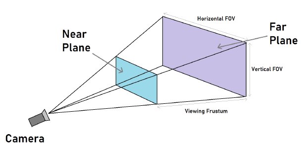
The sensor contains a set of four ‘cameras’, each with a 90° horizontal field of view (FOV), which capture depth and semantic annotation data for each of the four quadrants surrounding the sensor. The depth information provides distances to every pixel in each camera’s FOV, which can be interpreted as first-bounce rays. The corresponding annotation information tells the user the class of object at each pixel - with these, scattering modelling (e.g., Bi-directional Reflection Distribution Functions) can be applied appropriately.
Optional FOV overlap between cameras ensures continuity in coverage. It is left to the user to aggregate/register the data as appropriate for their needs.
Each camera outputs data in its respective orientation relative to the sensor. This provides readings at full 360° horizontal coverage in every frame. For rotating LiDAR models, the user can choose the appropriate horizontal ‘sector’ of this data with which to include in each frame, as their data.
Attachable and Dynamic:
The sensor is mounted to a configurable position relative to a vehicle in the simulation. This is similar to how the other positional BeamNG.tech sensors are placed, when used with vehicles (e.g., RADAR, ultrasonic, LiDAR, Camera).
It moves dynamically with the vehicle - tracking its position and orientation to maintain alignment with the vehicle’s motion and rotation. The user specifies a position relative to the vehicle center when first ‘attaching’ it, along with providing an orthonomal frame for pose through a ‘direction’ and ‘up’ perpendicular pair of vectors.
Data Output:
Each camera produces the following raw data in each frame:
A binary string representing depth values for every pixel, for all four ‘cameras’. The resolution of the sensor will determine how many pixels will be present in the data.
Corresponding annotation values which indicate the semantic class of the hit object (not available on all BeamNG maps).
Customizability:
Users can interact with the sensor through two APIs:
-
A Lua module, which implements some simple callback functions. The user can place this file in any location, and can write their own post-processing in it. It is described in more detail below.
-
A .dll example is also provided with the tool. The user can instead write their post-processing/implement callbacks in a compiled binary (.dll), which will provide optimal speed for their own algorithms. It is described in more detail below.
Inside either of these, users can implement ray marching algorithms, data aggregation, or custom image processing techniques or any desired combination, leading to an accurate LiDAR model.
Real-Time Updates:
The sensor updates its data output once every frame, providing fresh information synchronized with the simulation’s graphic time stepping scheme. These frames provide the ‘clock’ - on each ’tick’, a user callback function is executed in every frame, with the fresh raw data, ready to be processed into LiDAR imagery.
How It Works
Sensor Layout
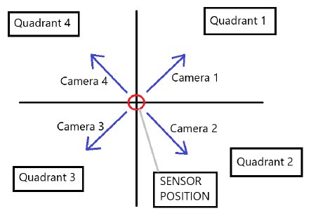
The Raw LiDAR Sensor utilizes four camera sensors positioned to cover a 360° view around the sensor. Each camera captures data for its quadrant as shown below:
Quadrant Mapping:
Q1: Upper right quadrant
Q2: Lower right quadrant
Q3: Lower left quadrant
Q4: Upper left quadrant
Each camera is angled diagonally to maximize coverage and ensure overlap where required.
Data Streams
Depth Data
A binary string representing the depth values of each pixel (32-bit floating points). This depth data is typically used to determine the distance of objects in the camera’s FOV.
Annotation Data
A corresponding array providing the semantic class of each pixel’s hit object (uint8 integer-valued). Examples of semantic classes include road, vehicle, building, etc.
Mounting and Movement
The sensor is attached to the vehicle in a user-defined position and orientation. As the vehicle moves and rotates, the sensor updates its position, orientation, and up-vector dynamically to maintain its attachment configuration.
Interfacing With The Sensor
Creating A Sensor
To first create (and start executing) a Raw LiDAR sensor, the user must use the BeamNG console (press ~ to open this). The following command can be typed into the command line at the bottom:
local sensorIds = extensions.tech_sensors.createRawLidar(be:getPlayerVehicleID(0), 'tech/rawLidar')
where the first argument tells the sensor to attach to the player vehicle, and the second argument provides the path of a user-created Lua module (called rawLidar.lua) where the appropriate callbacks have been implemented (see below).
Alternatively, if the user wishes to supply the path of the .dll, the following command can be used:
local sensorIds = extensions.tech_sensors.createRawLidar(be:getPlayerVehicleID(0), 'tech/rawLidar', {dllFilename = '/path/to/dll'})
where the extra (third) argument, in the form of a Lua table, provides the .dll path.
In each of the above commands, note that we have returned the ids of the camera sensors. The user can store these, or batch the command into a small Lua function which to call from the console and then store these in state somewhere. The ids can be used to remove the sensor later. An example of such a function is as follows:
function rawLidarTest()
  local vid = be:getPlayerVehicle(0):getID()
  local filename = 'tech/rawLidar'
  sensorIds = extensions.tech_sensors.createRawLidar(vid, filename)  -- eg store this in the module scope, for later usage.
end
which could be placed in, e.g., ge/main.lua, then executed from the command line like the commands above.
Note that even if a .dll is used, there must also exist a Lua module at the path given by the second argument (the .dll functions are called from there). Using a .dll is optional, however - everything can remain in Lua if desired.
User Lua Module
We have placed a default ‘User Lua Module’ at the location ge/extensions/tech/rawLidar.lua. We recommend the user examines the file. It is currently set up to work with a .dll, but the important thing to note is that this module implements three callbacks, described below.
onInit()
This callback is called once when the Raw LiDAR sensor is created. The user can use this callback to setup any state in the user Lua module, as required.
onUpdate()
This callback is called once in every graphics frame, as soon as the Raw LiDAR sensor is created. It contains in its signature, the current time step size (dt) along with the latest sensor readings data (depth1-4 and annot1-4, one per camera).
In the provided example, the onUpdate() callback simply takes this latest readings data and sends it to the .dll.
Note: It will take around 4-5 frames until the first data has returned back to the user, since dispatched must be sent to the GPU, computed, then the data returned to the caller.
onRemove()
This callback is called once when the Raw LiDAR sensor is removed. In the provided example, the onRemove() function callback simply calls a function in the .dll.
Note: to actually remove the sensor, the following command can be used:
extensions.tech_sensors.removeSensor(sensorId)
This should be called using all four ids returned when creating the Raw LiDAR sensor.
Users can access the sensor’s data and functionality in two primary ways:
User .dll
An example .dll source and CMake utility can be found at the location game/projects/tech/rawLidar. To build the .dll from the source, the user should read the readMe.txt file contained at this location. If the user prefers, it could also be built on e.g., Visual Studio. The .dll binary file can then be placed at the user’s preferred location. The path to this .dll should be adjusted appropriately when creating the Raw LiDAR sensor, in this case.
Examining the .dll source code in the example (bng_rawLidar.cpp), it contains an initialization data structure and some functions. The initalization data contains the sensor properties (they are hard-coded here and fetched by Lua). The functions can be anything the user requires, and will be called from the User Lua module. In this example, we simply mirror the three callbacks described above. The functions are essentially empty.
Initialization Data
Data used to set up the Raw LiDAR sensor is hard-coded in the example .dll, but the user could also place this in the User Lua Module file instead, if desired. This data is fetched when the Raw LiDAR sensor is created, rather than by having it specified in the creation command.
It contains the following:
-
posX(double): The X-position of the Raw LiDAR sensor, in vehicle space (i.e., relative to the center of the vehicle).
-
posY(double): The Y-position of the Raw LiDAR sensor, in vehicle space (i.e., relative to the center of the vehicle).
-
posZ(double): The Z-position (vertical) of the Raw LiDAR sensor, in vehicle space (i.e., relative to the center of the vehicle).
-
dirX(float): The X-component of sensor’s forward direction vector, in world space.
-
dirY(float): The Y-component of sensor’s forward direction vector, in world space.
-
dirZ(float): The Z-component of sensor’s forward direction vector, in world space.
-
upX(float): The X-component of sensor’s up direction vector, in world space.
-
upY(float): The Y-component of sensor’s up direction vector, in world space.
-
upZ(float): The Z-component of sensor’s up direction vector, in world space.
-
resX(int): The horizontal resolution of each camera’s image, in pixels.
-
resY(int): The vertical resolution of each camera’s image, in pixels.
-
fovY(float): The vertical FOV, in radians.
-
pNear(float): The near plane value (minimum cut off for camera readings), in meters.
-
pFar(float): The far plane value (maximum cut off for camera readings), in meters.
-
overlap(float): The signed overlap of the horizontal FOV, for each quadrant camera, in radians, e.g., 0.0 = 90 degrees horizontal FOV, i.e., no overlap between quadrants.
Readings Data
The depth data from each quadrant camera is a binary string (a string of bytes). The user can deal with this raw data in any desired way, but the following conversion code (written here in Lua) may provide convenient for converting each consecutive four-byte chunk into floating point values (the actual depths).
local function unpack_float(b4, b3, b2, b1)
  local sign = b1 > 0x7F and -1 or 1
  local expo = (b1 % 0x80) * 0x2 + math.floor(b2 / 0x80)
  local mant = ((b2 % 0x80) * 0x100 + b3) * 0x100 + b4
  if mant == 0 and expo == 0 then
    return sign * 0
  elseif expo == 0xFF then
    return mant == 0 and sign * math.huge or 0/0
  else
    return sign * math.ldexp(1 + mant / 0x800000, expo - 0x7F)
  end
end
If the user is writing in the .dll instead, something similar can be found for C/C++ etc.
The annotations data is already one-byte-per-value, e.g., local annotation1 = annotationData:byte(1), which will provide an integer value in the range [0, 255]. These values relate to whatever is used to map the annotations in the map.
Was this article helpful?


