Introduction
The Road Architect offers users a powerful and comprehensive tool for procedurally designing and creating detailed road networks that seamlessly integrate with other BeamNG features. With this tool, users can sculpt terrain using advanced terraforming tools, lay down a variety of roads and junctions, connect them, and then focus on detailing and accessorizing individual roads within the network. The tool provides a rich array of ready-to-use BeamNG objects and materials, including lamp posts, crash barriers, traffic lights, signs, and road markings.
The tool is designed with two main objectives:
i) To assist BeamNG users in generating road-based procedural content efficiently.
ii) To enable road networks to connect at the lane level, ensuring more natural and seamless integration with third-party road software compatible with ASAM OpenDRIVE.
Please note: This tool is still in development and should be considered a work in progress. As a result, future versions may not be fully compatible with the current version.
Preliminary Concepts
Before using the tool, it is important for users to familiarize themselves with a few key concepts:
Main Tool States
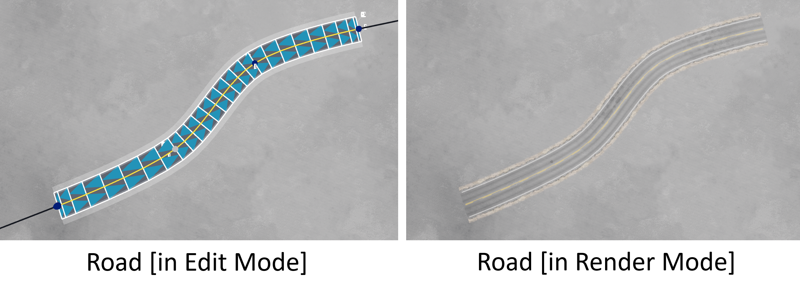
The tool operates in two distinct states which users can toggle between: Edit Mode and Render Mode.
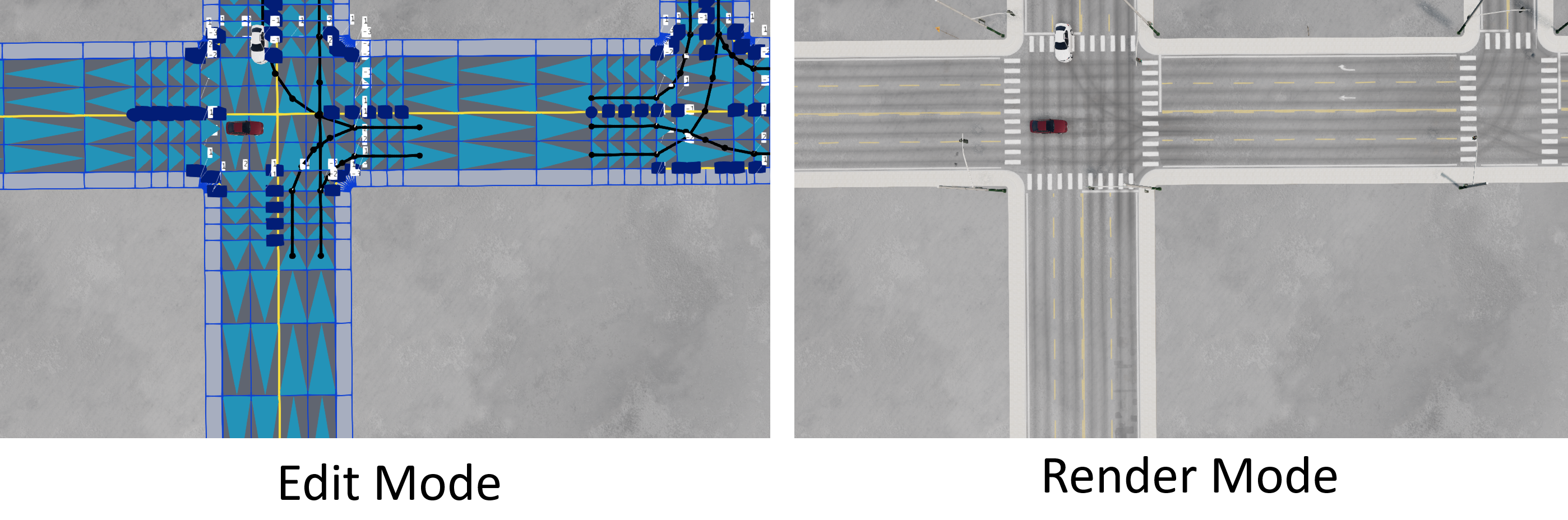
Edit Mode: This mode allows users to create and edit roads, sculpt terrain, and more. In Edit Mode, users will see visualizations of the roads in their editable form, rather than the final rendered versions. Roads in this state cannot be driven on, or navigate by AI vehicles.
Render Mode: In this mode, all roads are displayed in their finalized, rendered form. Decals and meshes appear, a collision mesh and navigation graph are generated, and users can drive on the roads or create traffic to navigate them. However, editing is disabled in this state, and the road network is considered “frozen.”
In typical usage, users will frequently switch between these two modes: first, building the road network in Edit Mode, then switching to Render Mode to test or view the final result. A convenient button for switching between the two states is located at the top of the main tool window.
Tool Primitives
The tool is built upon several basic building blocks, or ‘primitives’ which make up the session data. Below is a brief description of each for reference:
Roads:
Roads are the primary unit within the tool. A road consists of an ordered list of 3D nodes that define its path on the map. Various types of splines, such as standard spline, LSASL, and arc, can be used to create roads, each with different properties. Roads appear in the Roads List on the main tool window and can be created, edited, or removed in various ways. They can also be joined to other roads — sometimes requiring a transition block if the roads have different profiles — and can be split into multiple segments.
Road editing is described in detail here .
Nodes:
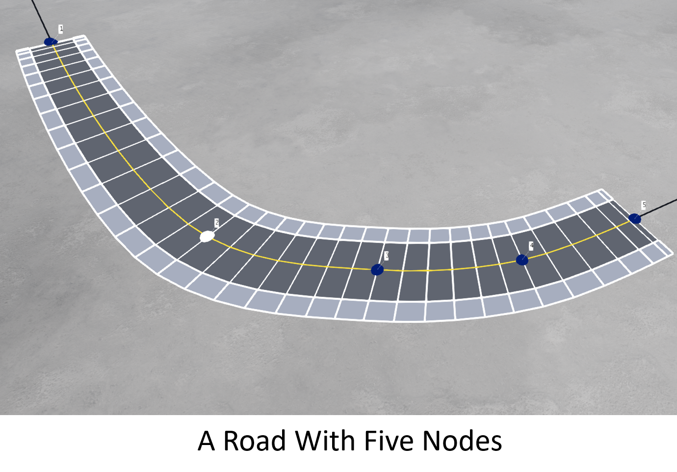
Nodes are unique to each road and can be translated (moved) on the map using the mouse or a gimbal. Nodes can be added, removed, or edited. The editing process includes adjusting lane widths and road banking at that node and other properties through a dedicated window. A Nodes List appears on the main tool window whenever a road is selected, providing various control options.
The following image shows a road with five nodes, where the second node is selected (note the different sphere color).
Bridges:
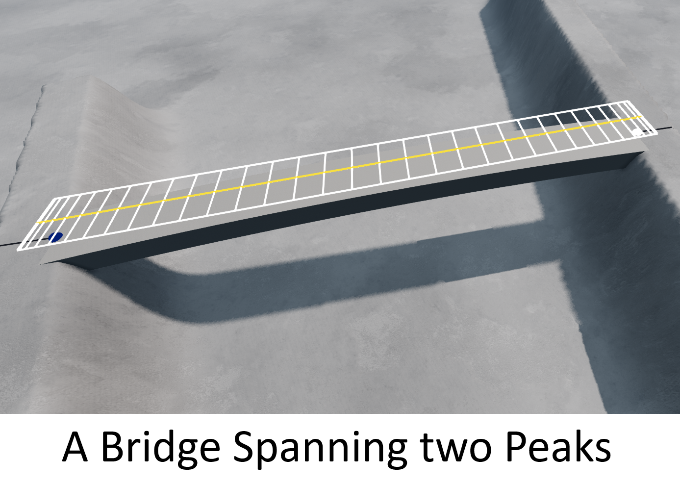
Bridges are a special type of road which also appear in the Roads List but are limited to two nodes (start and end). Unlike regular roads, bridges render as solid meshes even in Edit Mode. They are designed to span between elevated parts of the terrain and will attempt to merge seamlessly with the landscape at each end, allowing roads to be laid over them.
A specific button is available for recomputing the collision mesh, which should be used after positioning a bridge to ensure proper detection when placing roads on top of it. Bridges have a limited set of options and their nodes can be moved similarly to other road nodes.
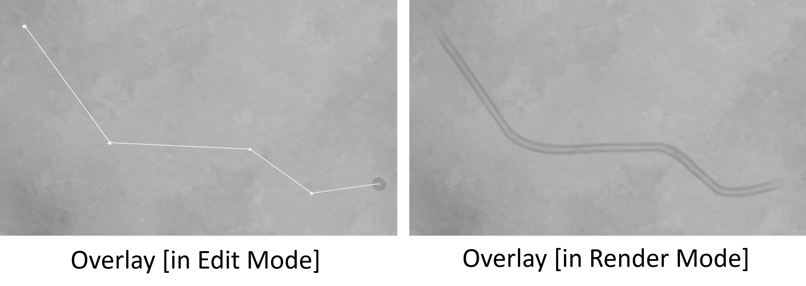
Overlays:
Overlays are another special type of road that also appear in the Roads List. They represent tire wear markings and are primarily used to add detail, such as making roads appear ‘dirtier’ or worn. Overlays come with a limited set of options and can be joined together or moved node by node using the mouse, as needed.
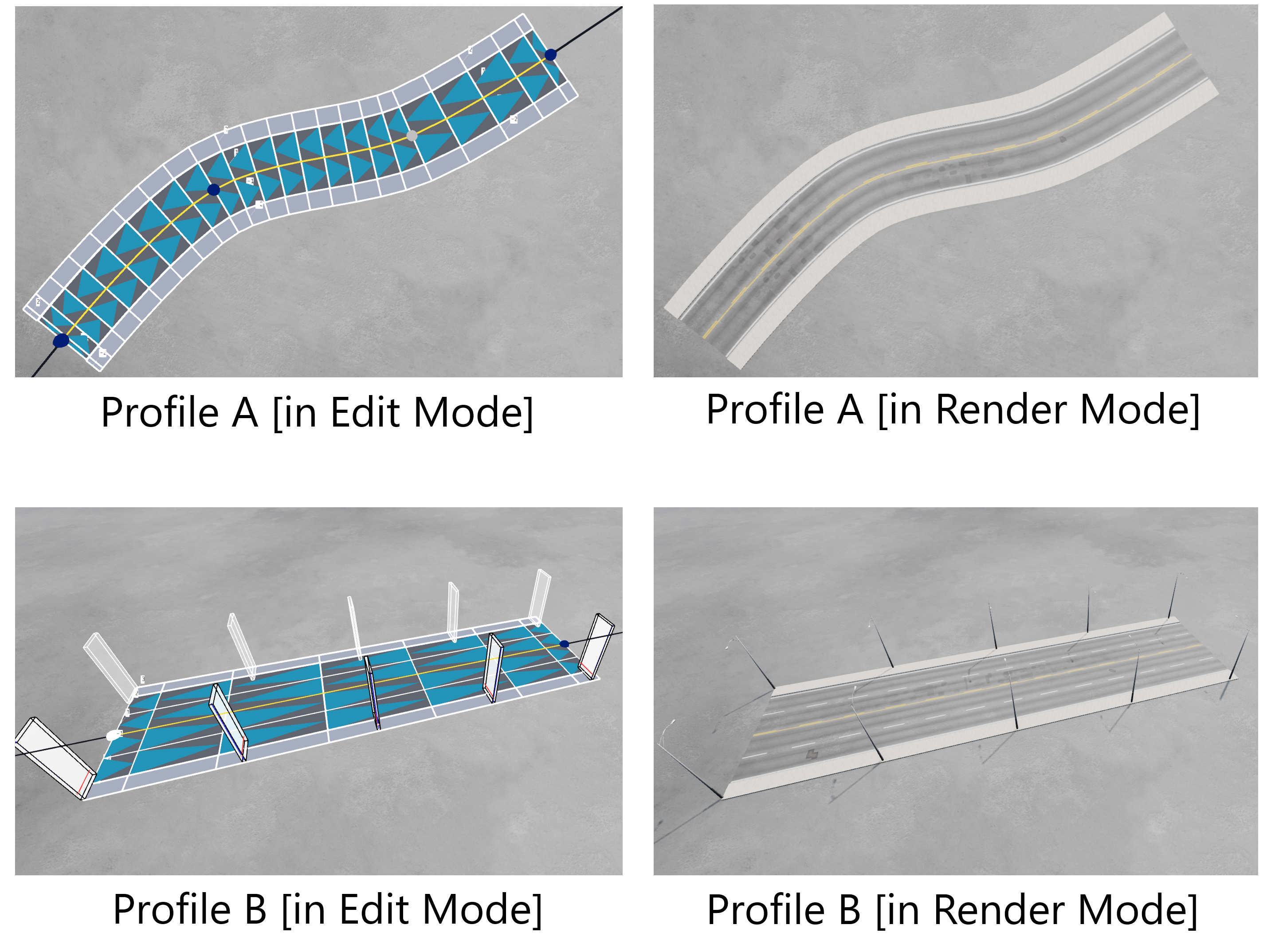
Profiles:
Profiles define the lateral (cross-sectional) structure of each road, including the number of left and right lanes, lane widths, and lane types. Users can edit the profile of each road, or select from standard preset road templates in the Profiles List Window. Additionally, users can create custom profiles, save them, and load them for later use. For example, a profile is the thing which distinguishes a three-lane highway with crash barriers from a two-way urban street with sidewalks and lamp posts. Profiles also include detailing layers, such as paint markings or edge blending. Profiles can be copied and pasted between roads for faster road creation. Profiles are described in detail here .
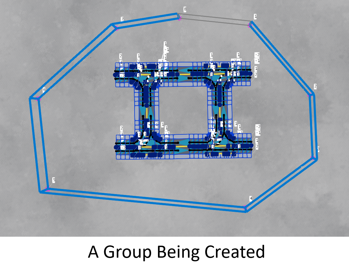
Groups:
Groups are collections of roads (and overlays, but not bridges) that work together, often because they form a junction or a key section of the road network. Users can create groups by drawing a polygon around the area of interest. Groups can be moved as a unit using the gimbal or rotated into place. They can also be saved to the Groups List for later use, which is particularly useful for duplicating common elements. Groups can be deleted, making grouping a useful tool for removing unwanted parts of a road network. The tool includes a collection of preset groups to help users quickly build road networks. Groups are discussed in detail here .
The following image shows a a collection of roads which the user is encircling with the ‘Create Group’ polygon tool, in order to turn the collection into a group.
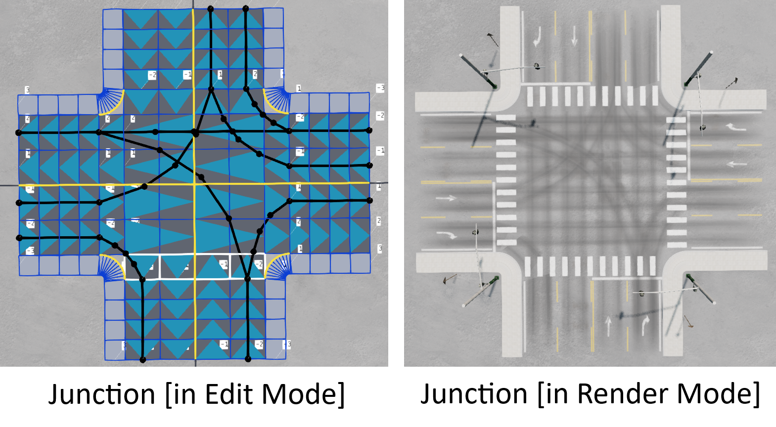
Junctions:
Junctions are similar to groups but may remain editable until the user decides to ‘finalize’ them. Users can design custom junctions based on various templates available in the tool, allowing the setting of properties such as the number of lanes, section sizes, and detailing. A convenient Junctions List allows users to select and place junctions on the map, with options for rotation. Junctions operate in two states:
Junctions-In-Edit: In this state, users can modify properties, but junctions cannot be connected to other roads.
Finalized Junctions: Once satisfied with the design, users can finalize the junction, moving its road over to the Roads List where they then behave like any other road. At this point, the junction can be connected to other roads, but it can no longer be edited. Upon finalization, the junction will be removed from the Junctions List.
Junctions are described in detail here .
Road Classes
While users have the flexibility to create any road profile supported by the tool, there are three main classes of roads that are used for pre-made content and junctions. Understanding these classes is important, as they determine whether roads can be connected. It is generally recommended to adhere to these classes:
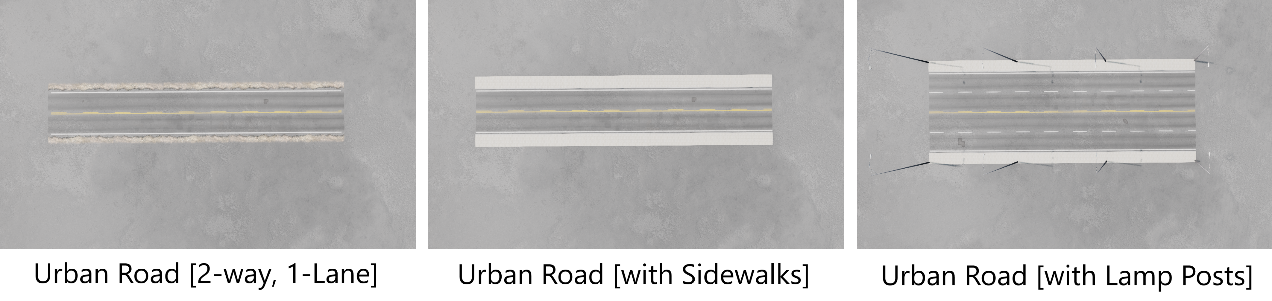
Urban Roads:
Urban roads are designed for towns, cities, and rural areas between built-up regions. They may include sidewalks but are not required to. Urban roads do not have a central reservation (the island between the left and right sides of the road) and should typically be symmetric, meaning the same number of lanes on the left and right sides. Rural roads may be considered a subclass of urban roads, typically featuring simpler, two-way layouts with one lane on each side and minimal detailing, such as the absence of sidewalks. However, rural roads are generally treated the same as urban roads, making the distinction minimal.
The following image illustrates some default urban road profiles in the tool.
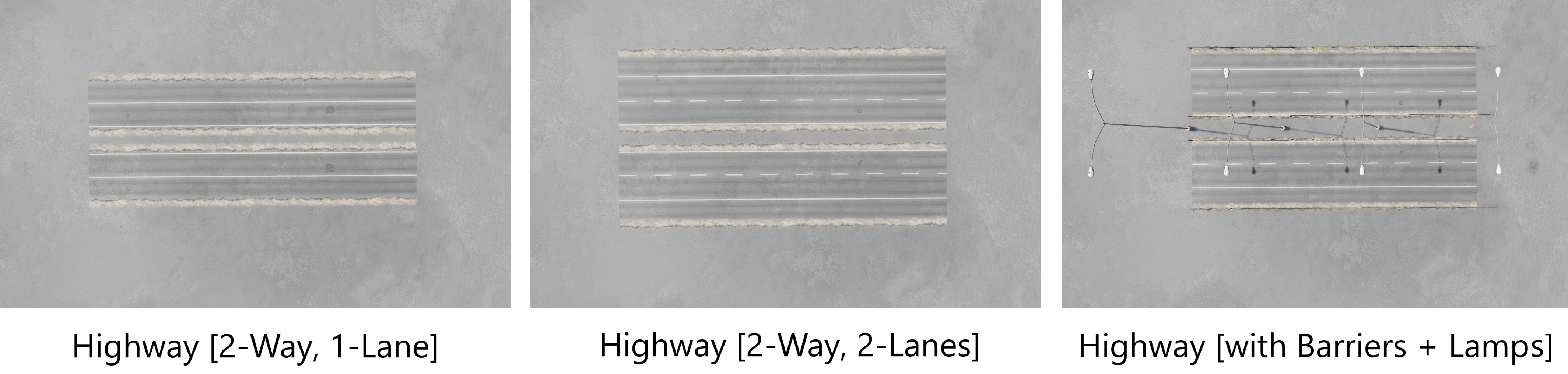
Highway Roads:
Highway roads are used for major routes that connect towns and cities or traverse urban areas. These roads must have hard shoulders on each side (the outermost lanes) and a central reservation, even if it is reduced to zero width, effectively disappearing. Highways cannot have sidewalks and, like urban roads, will typically be symmetric.
The following image illustrates some default highway road profiles in the tool.
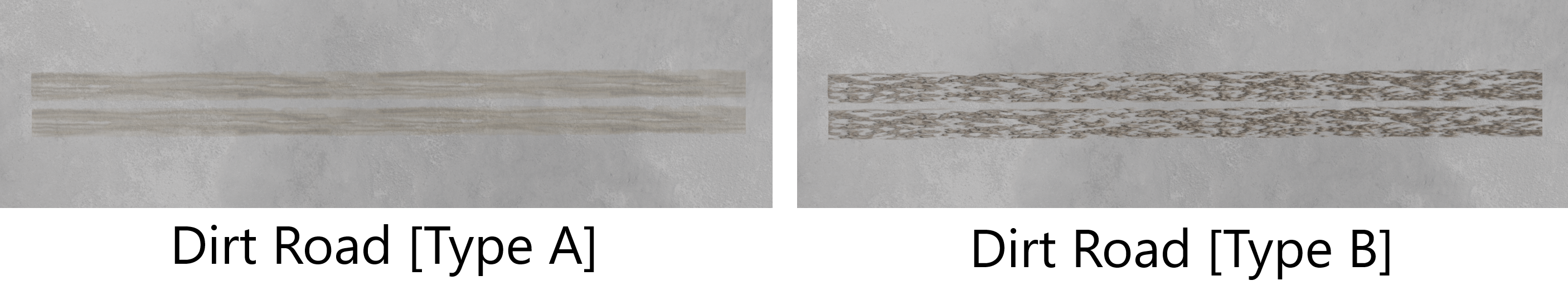
Dirt Roads:
Dirt roads represent unpaved trails or tracks, often found in forested or rural environments. These roads are simple, using a single material for rendering with no additional layers (such as paint markings) available for their customization.
The following image illustrates some default dirt road profiles in the tool.
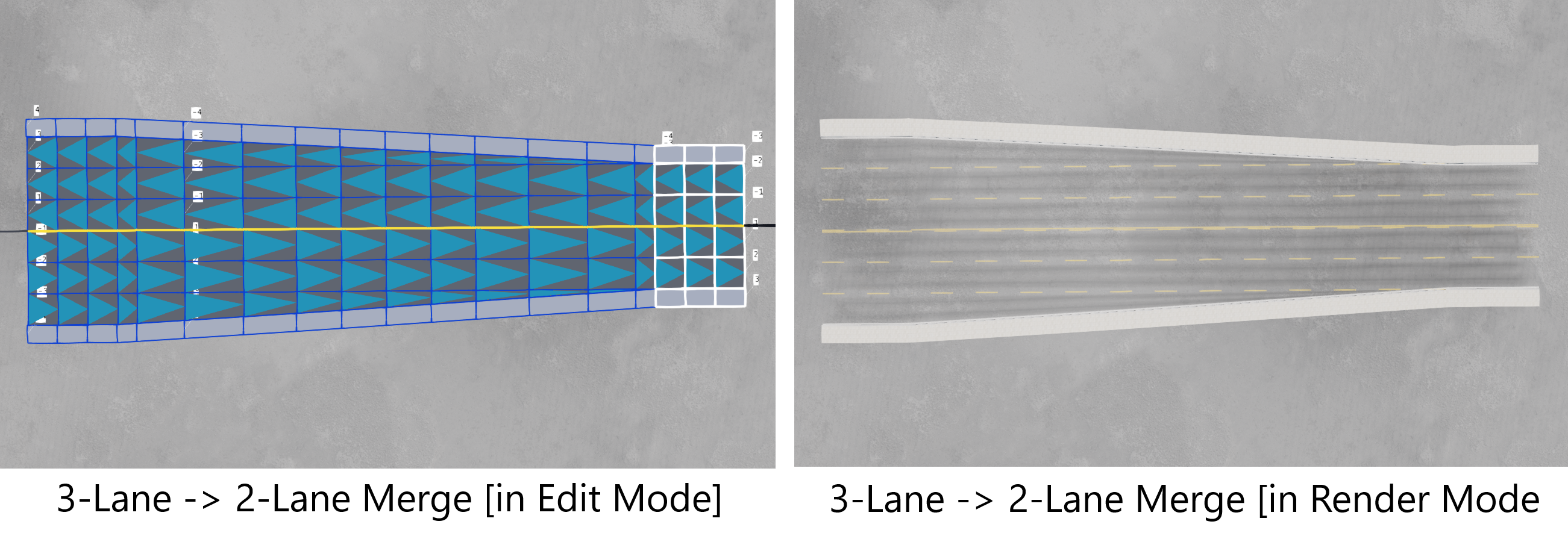
Road Class Compatibility:
Each of these main road classes are designed to link well within its own class. For example, users can connect a three-lane urban road to a two-lane urban road using a special ‘Merge Transition Block’. However, roads from different classes (e.g., urban roads and highways) are harder to connect except in limited cases. This separation gives each road class a degree of independence. That said, there are methods to link different road classes, such as using special Urban<->Highway Transition Blocks.
The following image illustrates the case above, where a two-way, three-lane urban road is merged into a two-way, two-lane urban road, using a ‘Merge Transition Block’.
Was this article helpful?