Road Editing
This page provides comprehensive details on creating and editing roads, covering all the available editing functionality. To begin detailed editing of any road, the user should select the Roads tab in the tool window. This is where all the features described on this page are found.
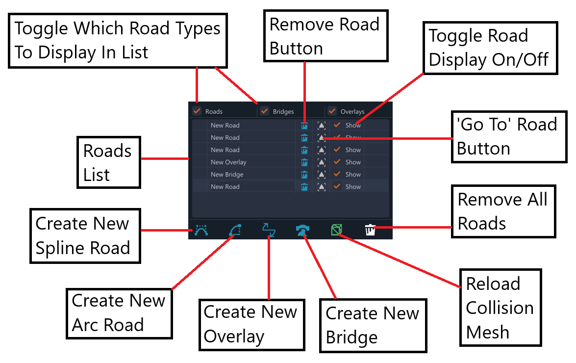
Roads List and Button Bar
In the Roads tab, you’ll find the Roads List along with a row of buttons directly below it. These are illustrated in the image below.
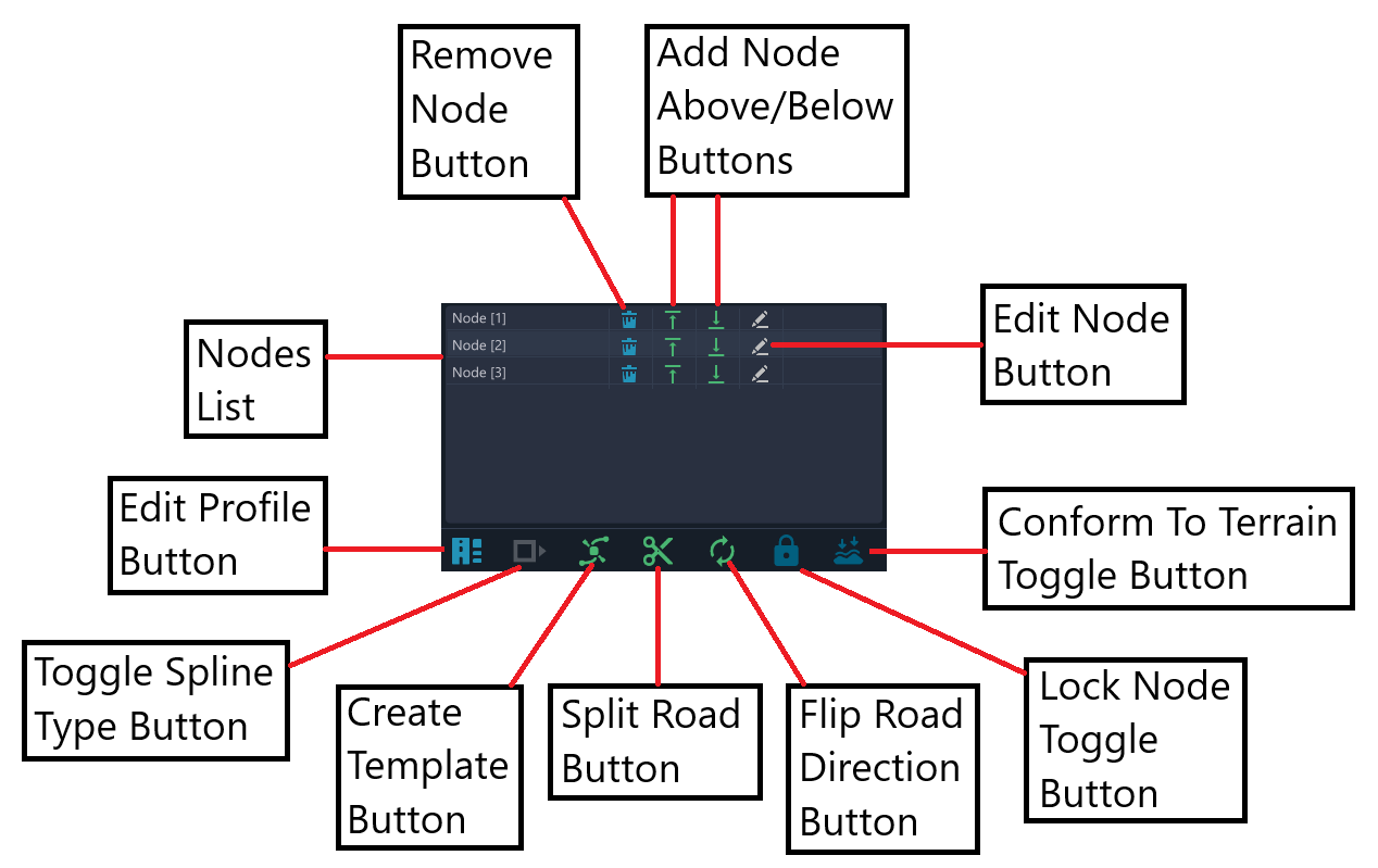
Nodes List and Button Bar
In the Roads tab, below the Roads List, you’ll find the Nodes List with another row of buttons beneath it. These are also illustrated in the image below.
Multi-Select
Multiple nodes can be selected, even across different roads, by holding down the SHIFT key while selecting nodes. When more than one node is selected, it forms a multi-selection. You can continue to add nodes to the multi-selection by keeping the SHIFT key held down. Some additional rules for multi-selection:
-
Using the shortcut CTRL + A, you can select all nodes in the currently selected road.
-
If you click on an already selected node while holding the SHIFT key, that node will be removed from the multi-selection.
-
If you release the SHIFT key and then click on another node, the multi-selection will be cleared, and the newly clicked node will become the only selected node.
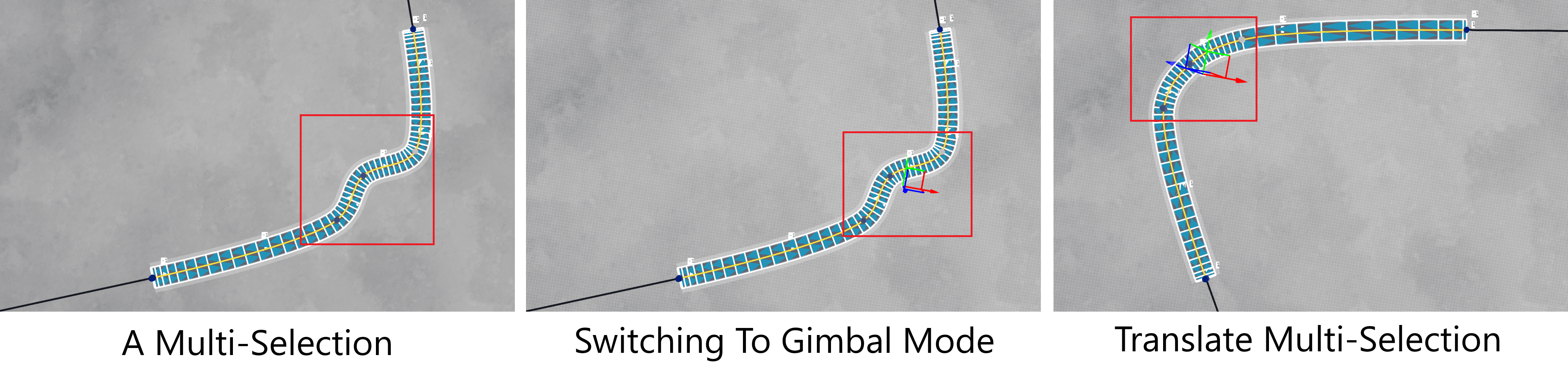
Multi-selections allow you to move multiple nodes together using the gimbal. The sequence of images below illustrates this process. The road shown has five nodes, with the central three nodes multi-selected. After making the multi-selection, the gimbal is activated (by pressing the ALT key) and used to translate the entire group in a single movement. Note that this preserves the local curvature of the road within the multi-selection while eliminating the need to move the three nodes individually.
Importing Decal Roads
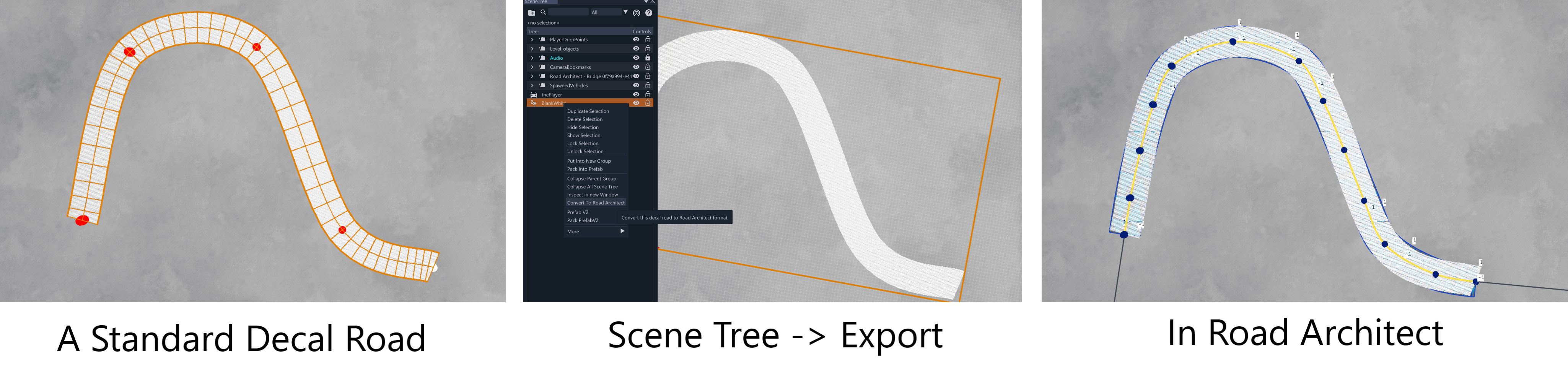
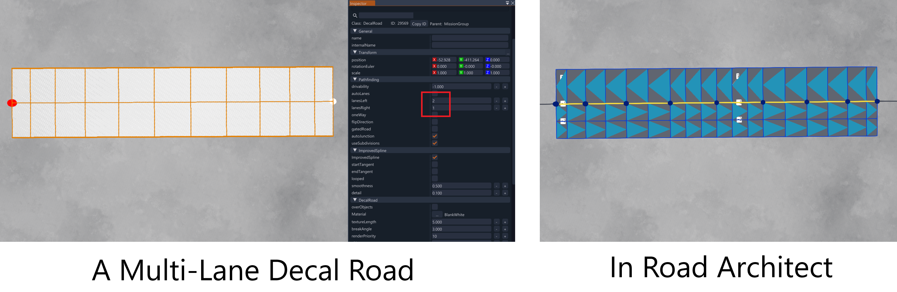
The World Editor allows you to convert native decal roads (such as those created in the Decal Road Editor) to the Road Architect format. To do this, navigate to the World Editor’s scene tree, select the decal road(s) you wish to convert, and right-click. In the menu which appears, choose the option “Convert To Road Architect” as shown below. You can then return to the Road Architect tool by clicking on its mode button. The converted road will appear in the Roads List, overlaid on the original decal road, as illustrated below. It is left to the user to decide whether to delete/hide the original decal road and keep the new version.
The fit may not be perfect, as some assumptions might have been made about the road, such as it being two-way or the number of lanes. However, if the decal road contained lane information, it will be inherited. The image below shows a decal road configured with two left lanes and one right lane (this can be adjusted in the Inspector window, with the relevant parameters highlighted in a red box on the image). Note that the centerline of the road is maintained, with the left and right half-widths evenly distributed among the respective lanes.
The tool can import multiple decal roads at once. To do this, simply select those which should be converted in the Scene Tree, then use the right-click menu to convert them to the Road Architect format, as shown in the image below.
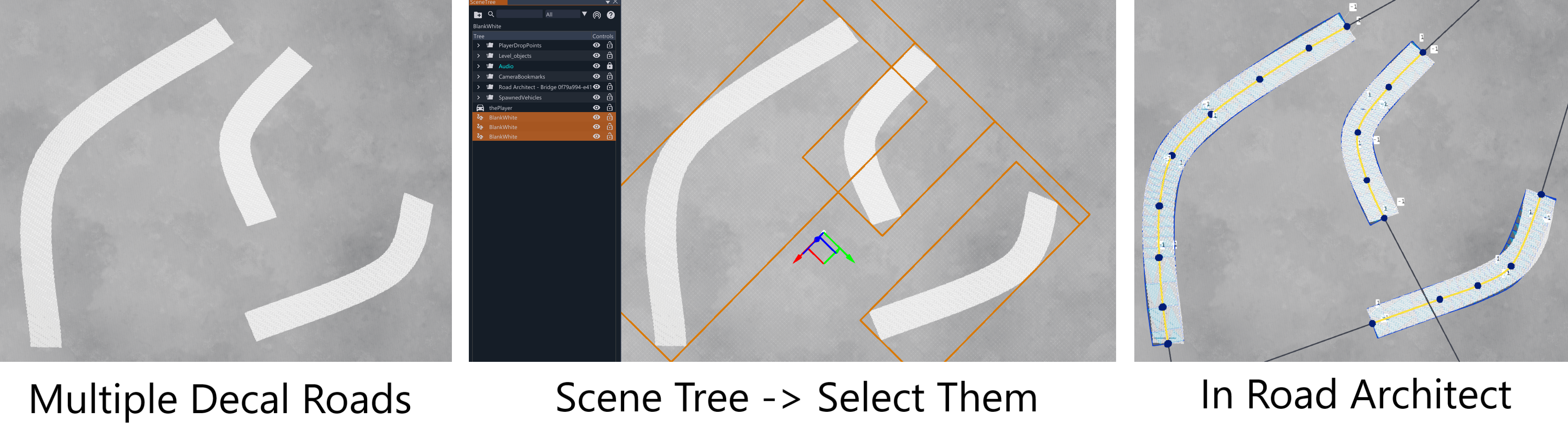 Importing Multiple Decal Roads
Cubic Spline Type
The tool provides three types of splines for users to choose from when creating roads. These are described below:
Standard Spline Type
This is the default spline type. As you draw nodes and add them to the road being constructed, a cubic polynomial spline is fitted through the nodes. Specifically, the tool uses centripetal Catmull-Rom splines, which offer favorable stability properties, making them well-suited for representing roads. The elevation component of the spline is computed separately to enforce monotonicity, preventing vertical overhangs in the road’s appearance.
Roads created with cubic splines are highly flexible and can represent a wide range of curvatures, making them a good general choice. However, the constraints used when fitting the road to the nodes may occasionally cause certain sections of the road to appear less realistic, potentially affecting the driving experience.
The image below highlights some key properties of spline roads.

LSASL (Line-Spiral-Arc-Spiral-Line) Type
The second type of road spline aims to create straighter, more realistic roads by utilizing geometric primitives commonly used by civil engineers in modern road networks. This type is also supported by ASAM OpenDRIVE.
This spline type builds roads in the following sequence: Line -> Spiral -> Arc -> Spiral -> Line.
The benefit of this method lies in its curvature properties:
Lines (L) have zero curvature, corresponding to a centered steering wheel with the wheels pointing straight ahead.
Circular Arcs (A) have constant curvature, corresponding to a fixed steering wheel position (not centered) when driving.
Clothoid Spirals (S) have linearly changing curvature, allowing for smooth transitions in steering, optimizing driver comfort.
The spirals transition between lines (zero curvature) and arcs (constant curvature), and vice versa. The image below highlights some key properties of LSASL roads.

Roads rendered with this spline type will appear straighter along their edges and can be made more rectilinear if needed (e.g., for creating precise 90-degree corners).
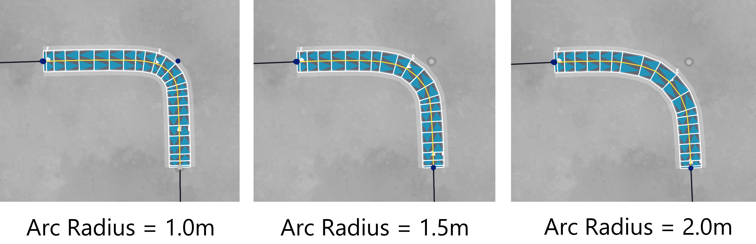
The Node Edit Window includes an additional slider for LSASL nodes: the Arc Radius Slider, which allows you to adjust the tightness or slackness of road corners. This slider is unavailable for the first or last nodes of LSASL roads since there are no arcs at those points. The effect of adjusting this slider is shown in the image below.
To switch between cubic splines and Line-Spiral-Arc-Spiral-Line splines, a toggle button is provided in the Road Edit Window. This can be done before drawing the road or applied to an already-created road to change its spline type.
Note 1: LSASL roads work best when the bend at each node is sufficiently large (e.g., greater than 45 degrees). Shallow angles can cause road folding and rendering issues, which are known bugs that need further investigation. However, very shallow angles (e.g., less than 10 degrees) should work fine.
Note 2: Our implementation approximates Clothoid spirals with cubic splines, as fitting true Clothoid spirals can introduce significant errors outside of special cases. However, the difference should be negligible to the user.
Arc Type
The third type of road spline consists of circular arc sections. A dedicated button in the Roads List Window is used to create these, as illustrated below.
Arcs are generated similarly to spline roads but are limited to three nodes only. This is because three non-collinear points are required to define a circle, from which the circular arc section is computed. The nodes can be moved on the map, altering the arc’s curvature and length. Elevations at each end can be adjusted to create upward or downward slopes, but note that the elevation of the center node is not used.
Since the road is represented discretely (as a piecewise-linear polyline), you may need to adjust the granularity using the Arc Granularity slider to achieve a smoother representation of the arc. If the granularity is too low, the arc may appear as a sequence of connected line segments (which it technically is), but increasing the granularity will make this less noticeable. The image below highlights some key properties of Arc Roads.

Road Guidelines
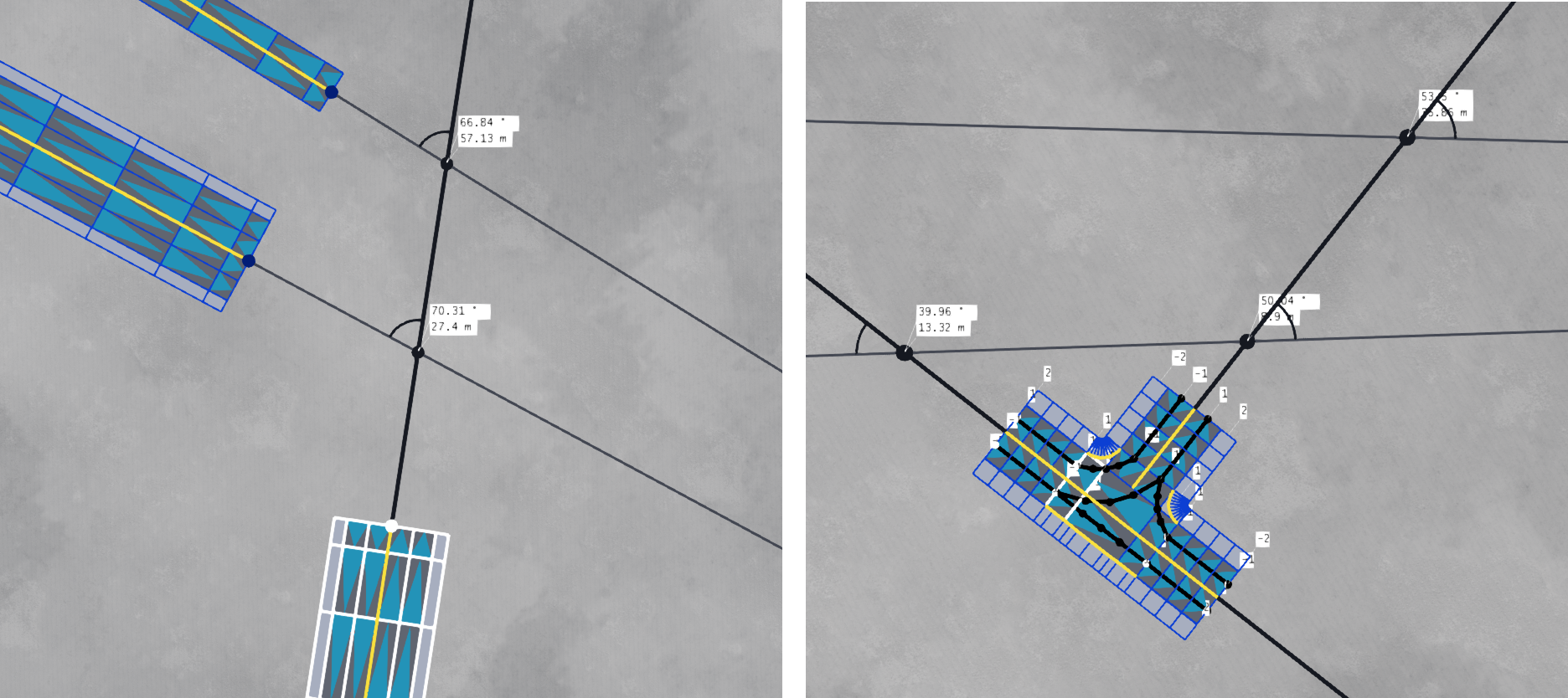
Road guidelines are straight lines that extend from the start and end of each road in the session. When the lines of the selected road intersect with those of other roads, spheres appear at the intersection points, along with text markups displaying the distance (in meters) and angle (in degrees). This feature is particularly useful for aligning roads and junctions and ensuring they are spaced at fixed distances.
When the terrain is uneven, the guidelines will attempt to render just above the terrain height, although parts of the lines may occasionally be obscured. If a road is elevated above the terrain, the guidelines still render just above the terrain, allowing intersections with other roads at different elevation levels.
The toggle switch for the guidelines is located in the tool window’s main control panel at the top and is only available in Edit Mode. The image below illustrates measurements made using the road guidelines feature.
The usefulness of road guidelines is best demonstrated in practice. The following sequence of images shows how to create a ‘city block’ from four crossroad junctions, using the guidelines to ensure everything stays aligned. The first sequence begins by aligning the first two junctions, then demonstrates how the guidelines assist in placing the third junction.
![Making A Block [part 1]](/world_editor/tools/road_architect/road_editing/blockCreateGuidelines.png)
The third and fourth junctions are added to complete the block, with the guidelines ensuring everything lines up correctly. In the final image, the appropriate junction exit roads are linked together, a process done after the junctions are finalized (as discussed later in the documentation).
![Making A Block [part 2]](/world_editor/tools/road_architect/road_editing/blockCreateGuidelines2.png)
The block appears as shown in the image below when switching to Render Mode.
![Making A Block [part 3]](/world_editor/tools/road_architect/road_editing/blockCreateGuidelines3.png)
Edge Blending
Roads often include special ’edge blending’ layers, which are designed to seamlessly blend the underlying terrain materials with the road — a common practice when creating BeamNG maps. You may have noticed that the roads themselves do not contain asphalt; instead, the asphalt is typically applied directly to the terrain as a material layer (specifically, the asphalt material layer). However, since terrains usually have a one-meter-per-pixel resolution, this can result in a ‘blocky’ appearance. Edge blending layers help to mask this and create a more convincing transition between the road and the terrain.
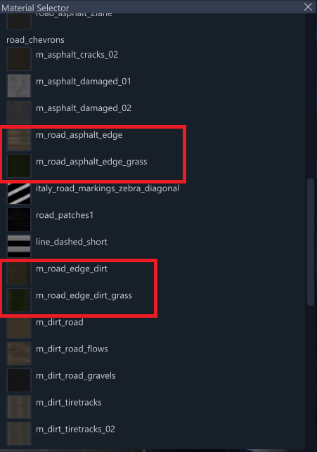
Various types of edge blending materials are available (e.g., for dirt, grass) and can be found in the material selection list. These are highlighted in the image below.
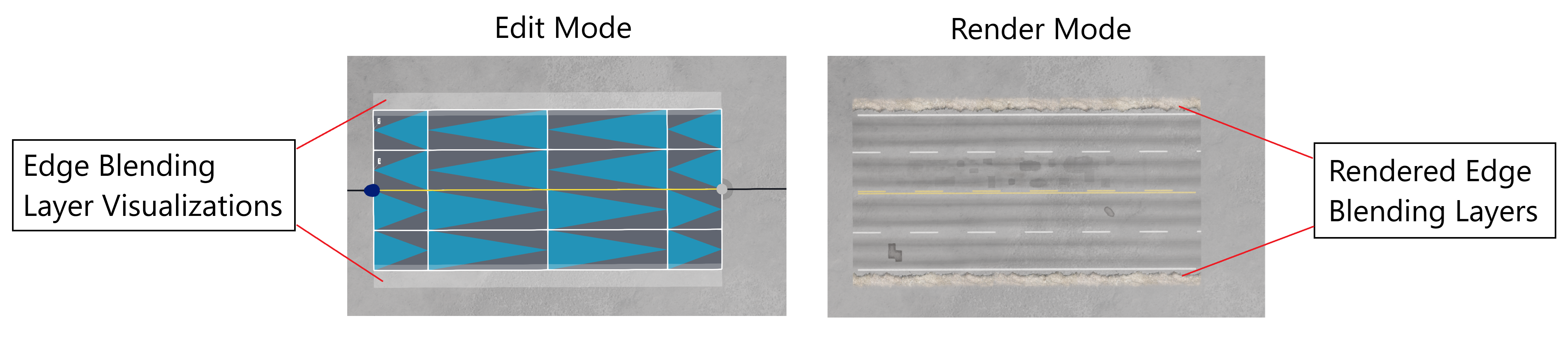
The following image shows how some of these materials appear when rendered as edge blending layers.

Note: If you wish to disable edge blending, you can either remove the layers from the road layers (see the layers section below) or set the edge blending material to ‘invisible’ (also found in the materials list). The latter approach may be particularly useful for junctions rather than roads (discussed later). Some roads, such as those with sidewalks, do not include any edge blending layers.
The examples below show roads with edge blending to illustrate its purpose.
Bridges
Simple bridges can be created to span gaps in the terrain, such as valleys between two peaks. These bridges are made from procedural meshes, and roads can be laid on top of them. The key feature of these bridges is their ability to blend seamlessly into the terrain at each end (assuming the terrain is flat enough at each end).
To create a new bridge, select the corresponding icon from the button row below the Roads List. You will then be prompted to place two nodes on the terrain, ideally on either side of the gap for the best results. The nodes can be moved in the same way as road nodes. You may need to adjust the node positions slightly to achieve the best fit with the terrain. This may require some manipulation or, in some cases, even some terraforming to achieve a good blend.
In addition to moving nodes, bridges have several control parameters that can be adjusted to shape the bridge:
Bridge Width: Controls the lateral width of the bridge in meters.
Bridge Depth: Controls the height (bottom to top) of the bridge in meters.
Bridge Arch Amount: Adjusts the shape of the bridge arch by setting the relative height offset of the bridge midpoint, which can be positive or negative.
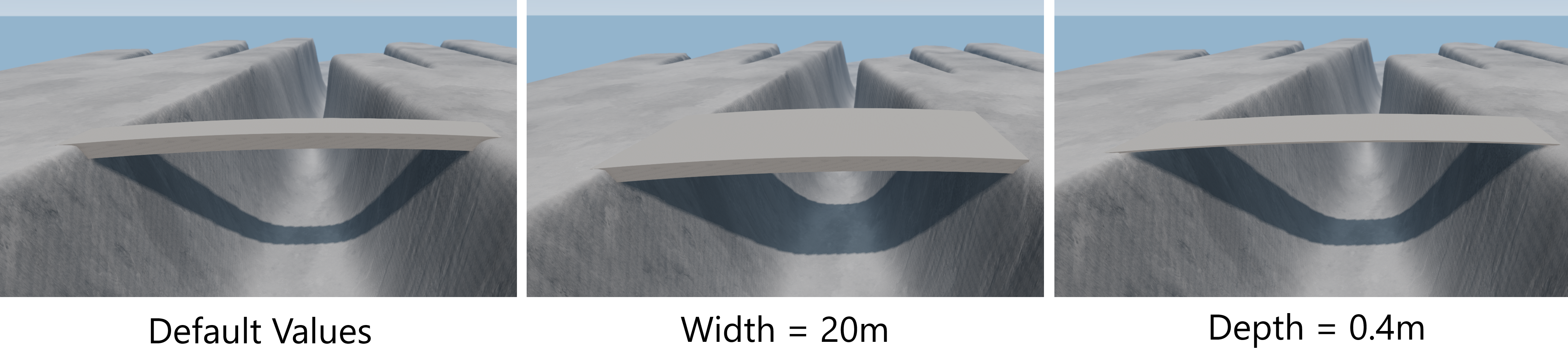
The following images show a typical bridge with the default parameters and when the width and depth are set to different values.
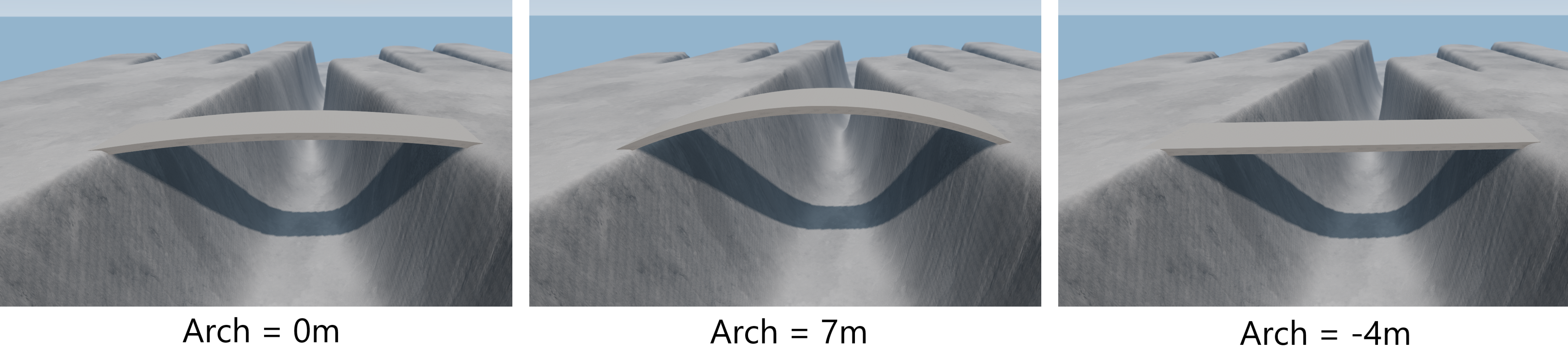
The arch of a bridge may need to be adjusted if the depth is changed. For a bridge with a depth of two meters, the image below illustrates the effect of setting various values for the arch amount.
An important button can be found under the Roads List window, next to the button used to create the bridge. This button is used to re-compute the collision mesh and appears as follows:
 Re-Compute Collision Mesh Button
When a bridge is created or moved, it is good practice to re-compute the collision mesh. This ensures that the bridge can be detected when you attempt to place road nodes on top of it. If this step is skipped, the mouse cursor may sink through to the terrain below the bridge, making it difficult to position nodes correctly. Note: The collision mesh is automatically re-computed when entering Render Mode and remains active when reverting to Edit Mode, so this could be an alternative. Keep this in mind if you encounter any unexpected behavior when using bridges.
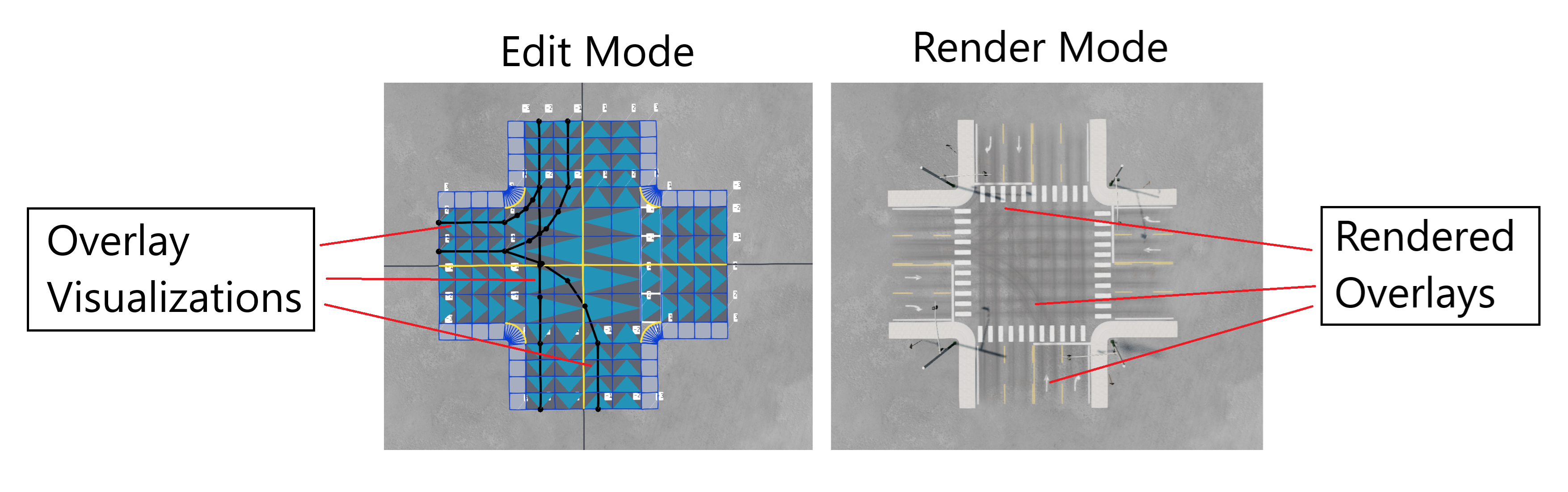
Overlays
Overlays, also known as ’tread overlays’ are a special type of spline used to add tire tread markings along a path, typically on top of a road. These overlays are primarily used for cosmetic purposes, enhancing the realism of roads or junctions. This image below shows this effect on a four-way crossroads style junction.
Overlays are treated similarly to roads and therefore appear in the Roads List alongside regular roads and bridges. They can have any number of nodes, which can be moved in the usual way. Overlays can also be joined end-to-end with other overlays or split as needed.
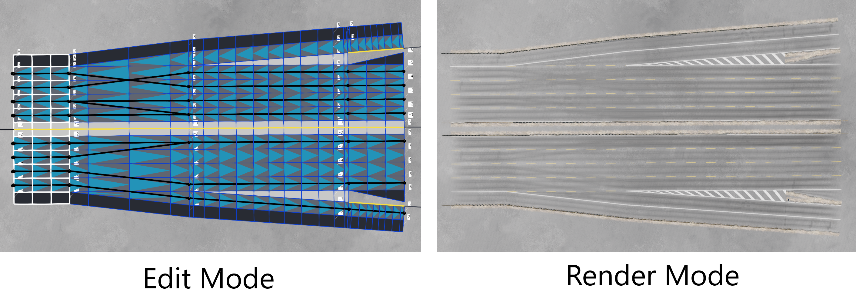
Overlays commonly appear with junctions, as shown in the examples below: first, an urban junction, followed by a highway junction.
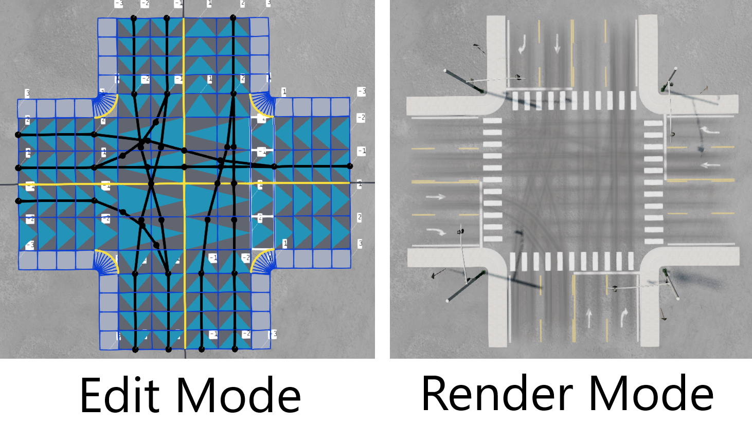
 Overlays On A Highway Junction
Mouse And Keyboard Shortcuts
The following is a list of useful shortcuts for the user’s reference:
Mouse:
- Double-clicking a node will snap it to the surface below, handy if it’s in the sky.
- Right-clicking the mouse is used to get rid of multi-selection.
Keyboard:
- Pressing ALT toggles the gimbal on/off.
- Holding SHIFT and then selecting nodes can be used to make multi-selections.
- Pressing CTRL + A will select all the nodes in the selected road (multi-selection).
- Pressing DEL removes selected node.
- Holding CTRL and moving the mouse wheel will change the width of the road at the selected node (all lanes together).
- CTRL + C will copy the profile from the currently selected road. CTRL + V will copy the profile (if copied) to the currently selected road. Can be used to duplicate profiles across many roads very quickly.
Miscellaneous:
- Selecting a group or junction from the respective lists will multi-select it.
- Junctions/groups can be rotated only in gimbal mode. This is done by holding down the left mouse button then dragging the mouse up or down. Holding down SHIFT will provide more precision (ie rotate slower).
Node Edit Window
Each road node can be further edited using the Node Edit Window. This window displays the implementation of the road profile template at the specific node (e.g., lane widths, lateral rotation, etc.), and adjustments can be made here. However, the profile itself cannot be changed in this window. The image below provides a description of the window.
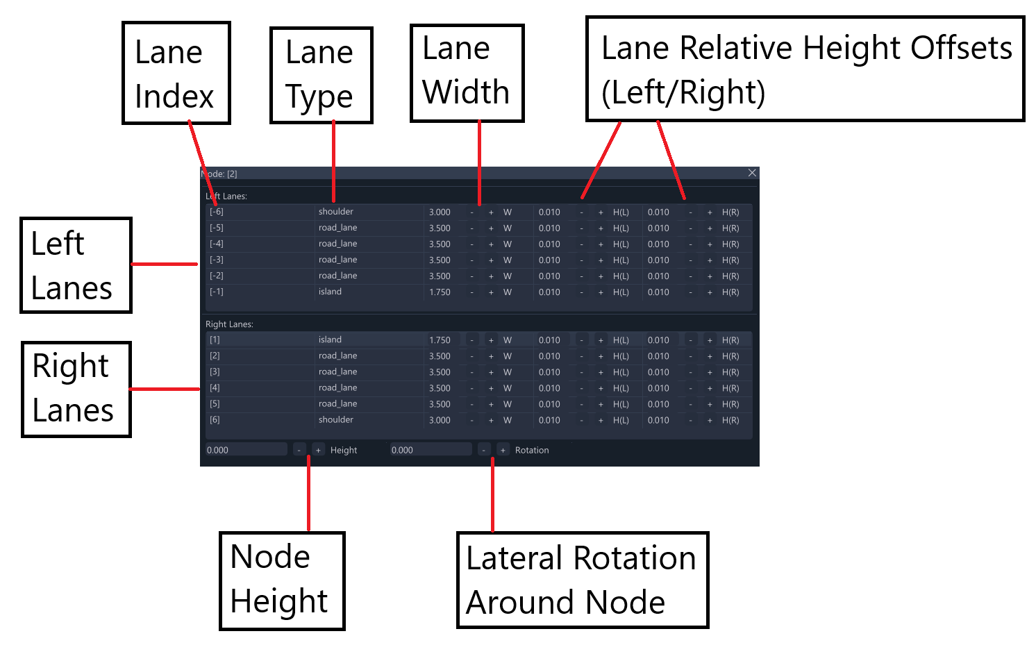
Setting the lane width applies to any type of lane (e.g., road, sidewalk, shoulder, island). However, the relative height values are only effective for sidewalk lanes. The edit visualization will still show the lane as raised for any type, though.
Note: The lateral rotation box in this window is the only way to adjust the road’s lateral camber.
Terraform Control
The tool provides various options for terraforming, allowing the user to modify and conform the terrain to the road(s). This feature enables roads to be set at different elevations and inclines, or can be used creatively to sculpt mountains and valleys by using roads as a sculpting tool.
Note: Terraforming operations support Undo/Redo functionality (using the CTRL + Z and CTRL + Y commands, respectively), so any unwanted changes can be quickly undone.
Terraforming Single Roads:
The user can terraform the terrain to suit a single road using the controls found in the Terraform Control section, located under the Nodes List in a dedicated collapsible header.
The button in this section initiates the terraforming operation, applying the parameters set by the Domain of Influence and Margin sliders. Terraforming is explained in more detail in a later section of this documentation. The image below illustrates a terraforming operation performed on a road using two different sets of parameters. In the left image, the Domain of Influence and Margin are larger than in the right image.
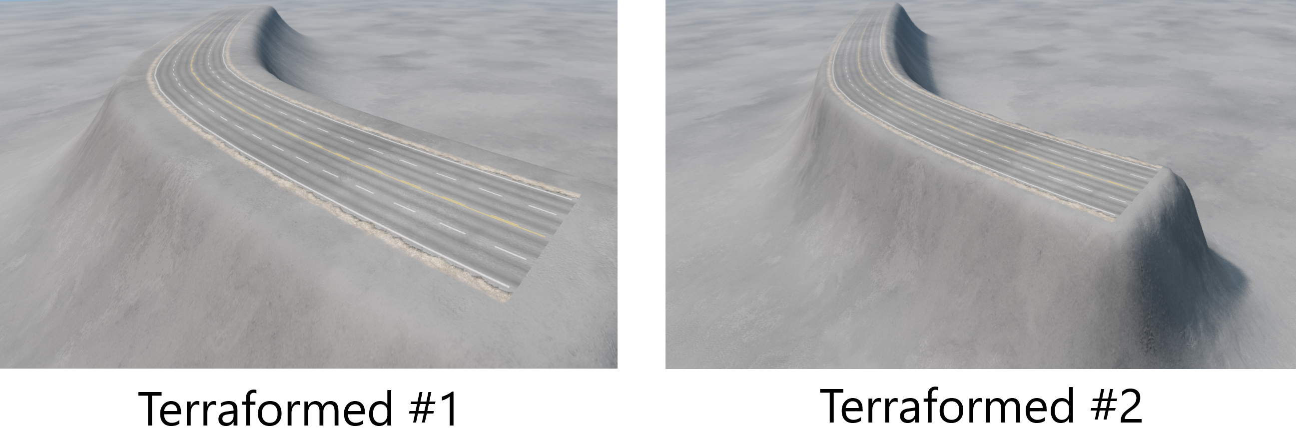
Note: When terraforming the terrain for a single road, the operation doesn’t account for nearby roads, which may result in the terrain “growing” over or under them. Be mindful of this, and use the terraforming visualization to avoid such issues.
The terraforming controls also offer a range visualization with which the user can see how far the terraform will extend into the terrain. This is switched on using a convenient checkbox under the collapsible header. The image below shows the visualization being used to terraform a single road.
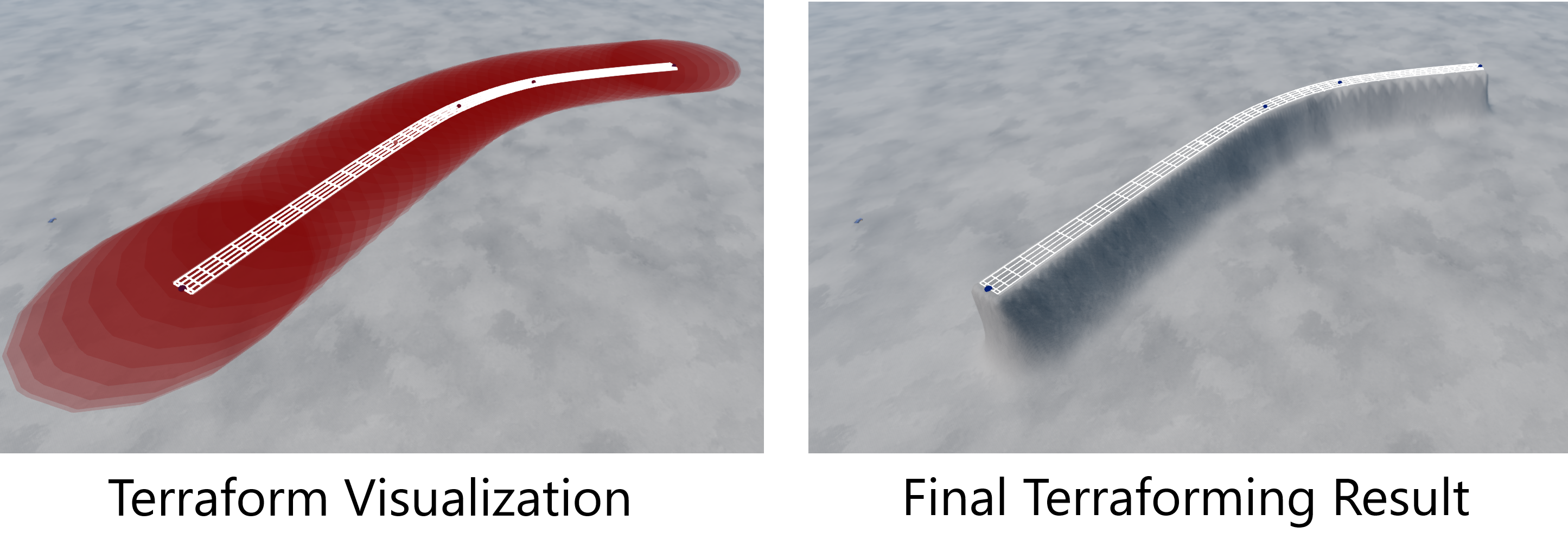 Terraforming Range Visualization
Note: Terraforming can also be applied to all roads in the session using a separate button. All terraforming operations are described in detail later in the documentation.
Terraforming Groups:
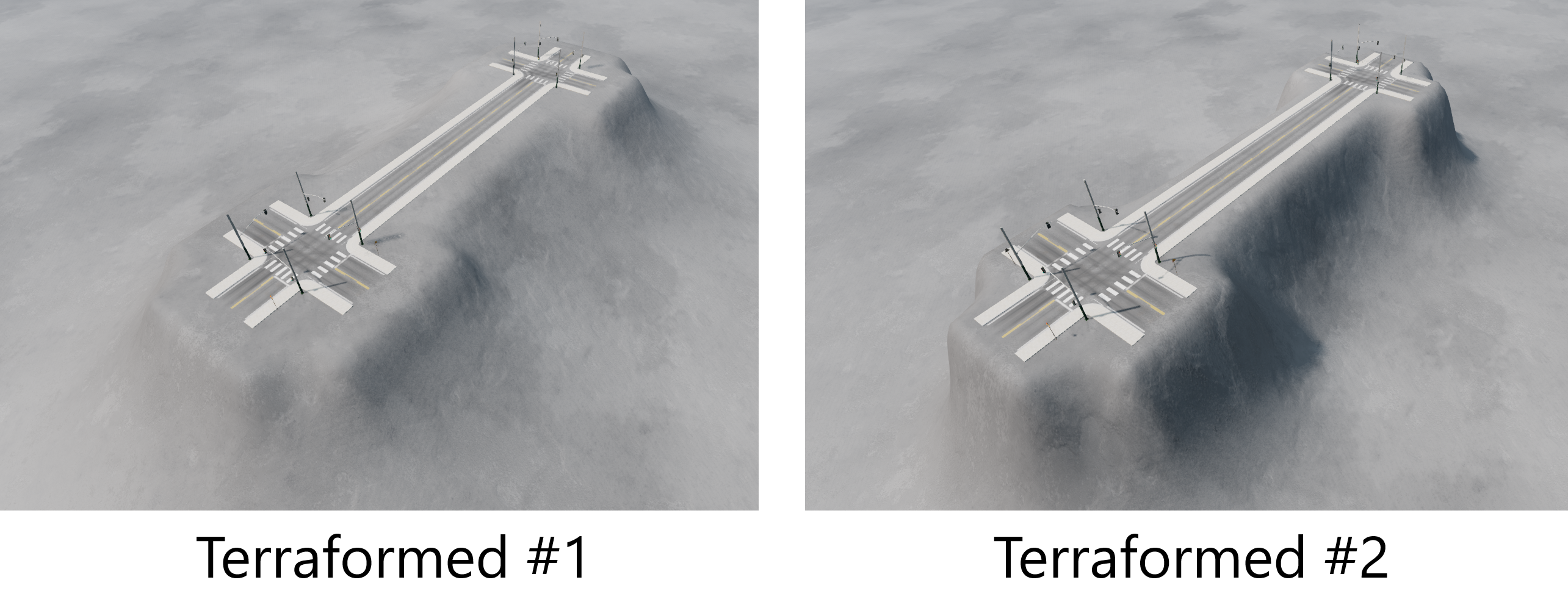
The user can also terraform groups of roads. In this case, all the roads within the group are considered together. This process is explained in more detail in both the groups section and the terraforming section of this documentation. The image below shows terraforming being applied to a group of roads consisting of two junctions and the connecting road between them.
As with the single road case, there is a range visualization option for use when terraforming groups. The image below shows the visualization being used to terraform a group.
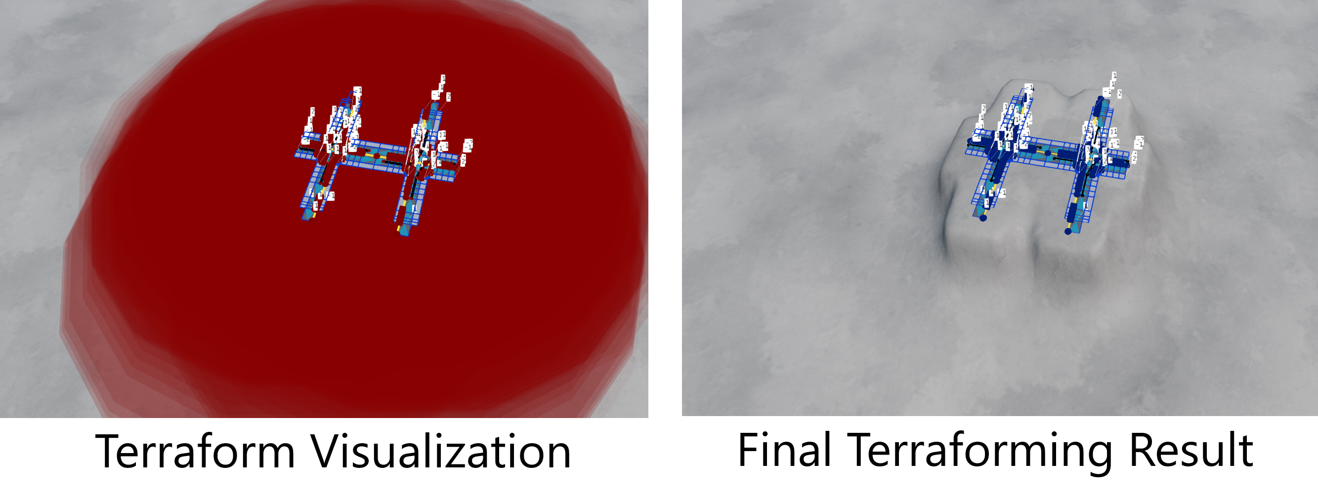 Terraforming Range Visualization For Groups
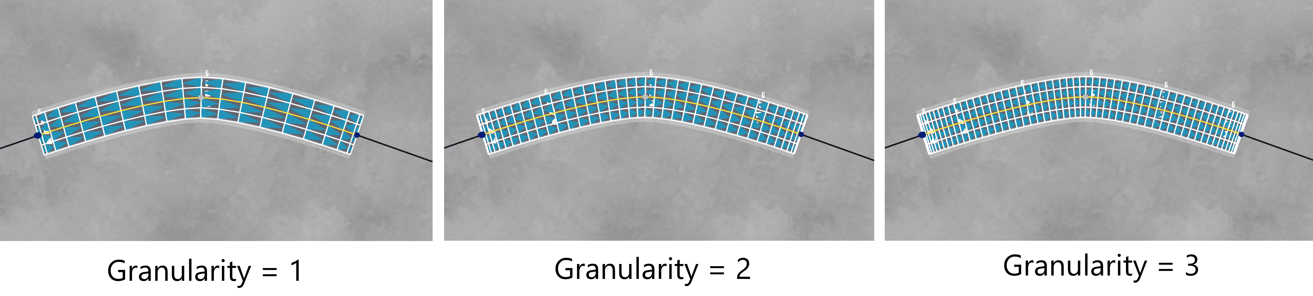
Granularity Control
The granularity (or discretization) of the road can be adjusted under the Granularity Control section below the Nodes List. This is a collapsible header, and is shown in the image below.

Using the highest level of granularity, and sometimes even the second highest, can occasionally result in rendering issues (such as some road details not appearing). This is a known issue with the engine and will be addressed in a future update. In the meantime, if you encounter this problem, try using a lower granularity. There are three levels available, illustrated in the image below.
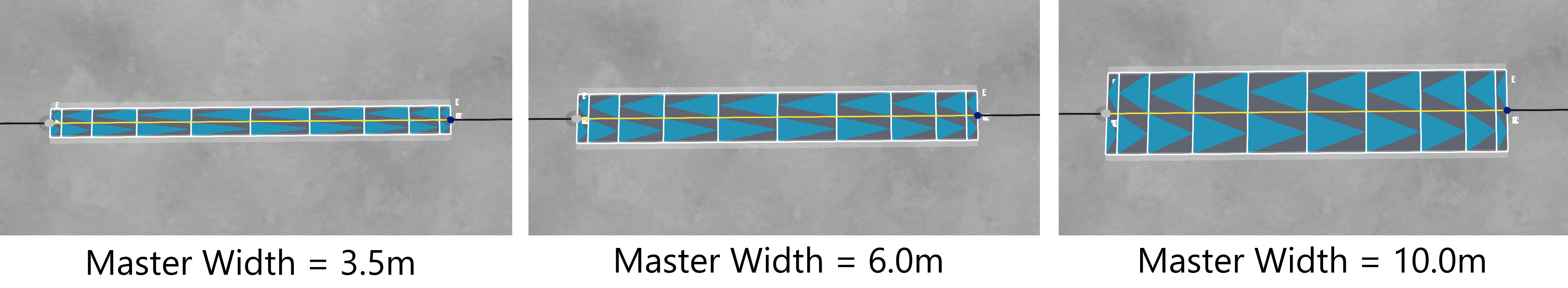
Master Width Control
The Master Width Control section contains a slider that allows you to quickly set the width of all lanes in the selected road. This is a collapsible header, and is shown in the image below.

Note: This will overwrite any local adjustments made to the road, such as nodes with customized widths for tapering inward or outward. The image below shows the effect of setting various widths on a road using the Master Width control.
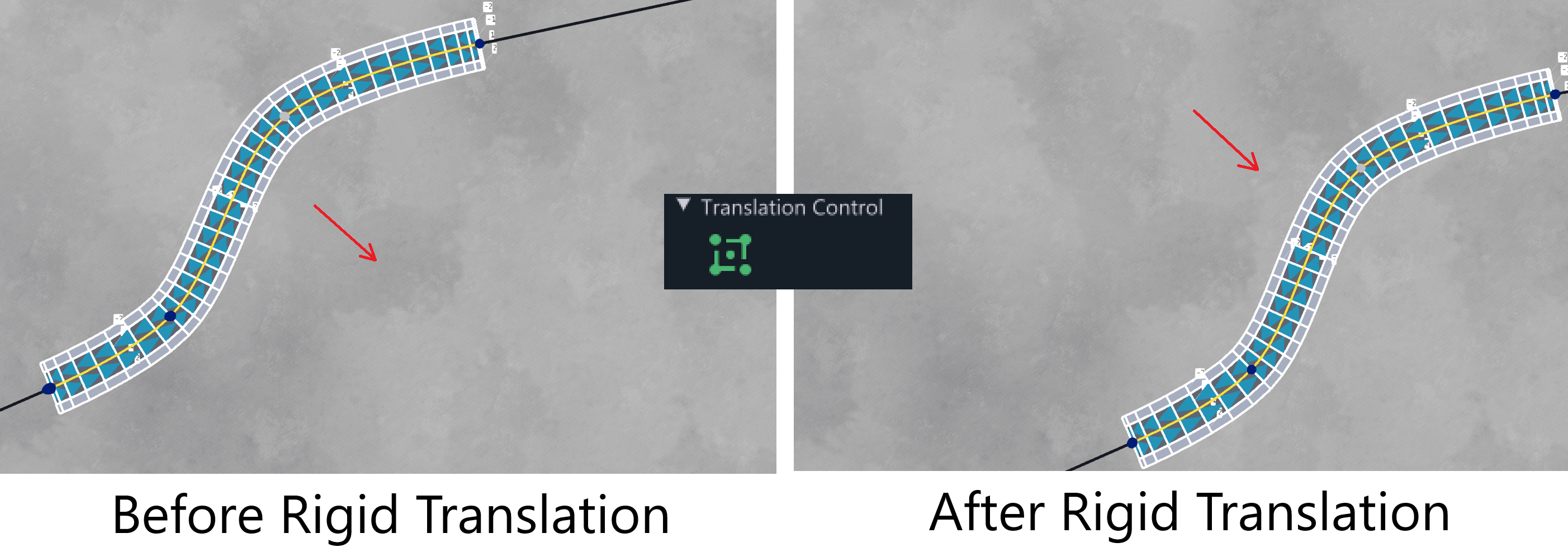
Translation Control
Controls for moving the road can be found in the Translation Control section. This is a collapsible header, and is shown in the image below.
By switching the Rigid Translation toggle button on (found under the Translation Control header), the user can move the entire road by dragging any of its nodes. The image below demonstrates a rigid translation, where every node in the road has been moved by the same vector.
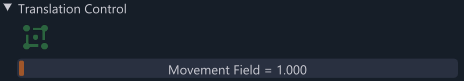
Under the same header, you can adjust the Movement Field. This slider controls an invisible “force field” around the selected node and is only active when Rigid Translation is not in use. Sliding it to the right increases the radius of the field, measured in meters. When moving nodes within this field, neighboring nodes will also shift slightly, helping to preserve the angles between them. This feature allows for smoother adjustments to the road position, and experimenting with it will help you understand how it works. The sequence of images below shows a force field translation applied to the node highlighted by the red box. As the node is moved, the neighboring nodes also shift slightly, allowing the road to retain some smoothness as it is adjusted.
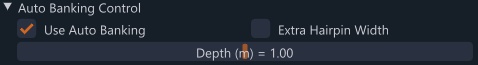
Auto-Banking Control
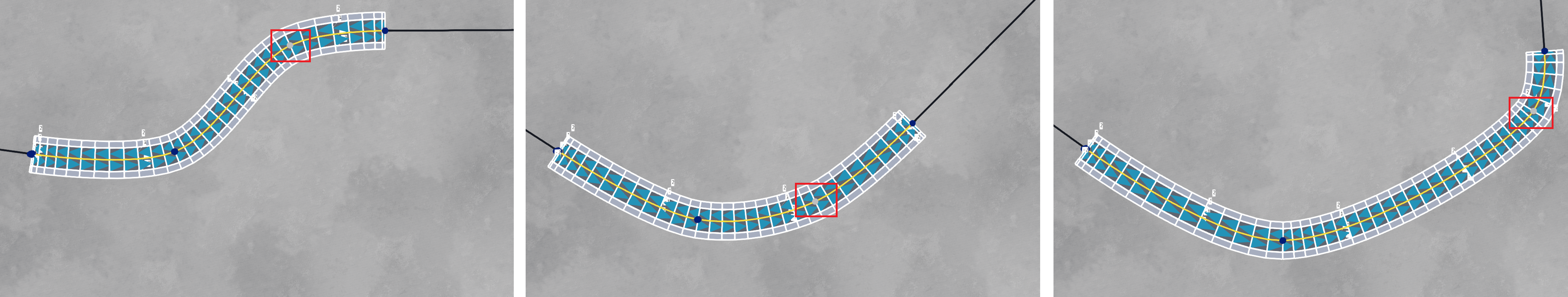
Auto-banking is a feature that adds natural banking or camber to a road. When the road curves to the left, it will bank slightly to the left; when it curves to the right, it will bank slightly to the right. As the road is adjusted, the auto-banking will adapt to the new curvature at each node. The image below shows an example of a road using auto-banking.

The degree of banking can be controlled with the associated slider found in the Auto Banking Control section. This is a collapsible header, and is shown in the image below.
Here are some important rules regarding the auto-banking feature:
-
If auto-banking is enabled, the banking at each node will be automatically adjusted, overwriting any manual changes made in the Node Edit Window.
-
If auto-banking is turned off after being enabled, the existing banking will remain, but it will no longer adjust as the road is moved.
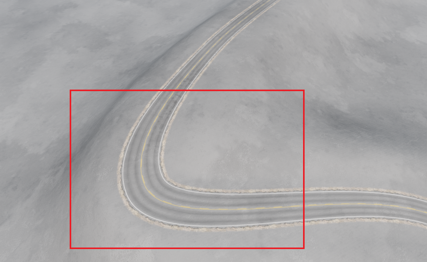
The Extra Hairpin Width checkbox, when enabled, adds extra width to the road at nodes with a sharp curvature. This feature is particularly useful for rural or mountain roads with tight bends and is often used in conjunction with auto-banking. The image below shows the effect of setting the checkbox - the highlighted corner has had its width increased slightly.
Layers
Layers are a powerful detailing sub-tool in Road Architect, allowing you to add various details to a road, such as decal roads, decals, or static meshes, in a render-ordered list. This procedural tool streamlines the process of adding elements like road edge lines, jittered lamp posts, bollards, and crash barriers along the road. Instead of placing each item individually, you can apply them with just a few clicks. The edit visualization provides cues as to how each layer will be displayed on the selected road.
The properties for these layers can be found under the Layers Section below the Nodes List. When the Layers Section is expanded, all the layers currently associated with the road will be displayed in the Layers List. Most roads will already have some default layers, such as paint markings or edge blending. The Layers List is described in the image below.
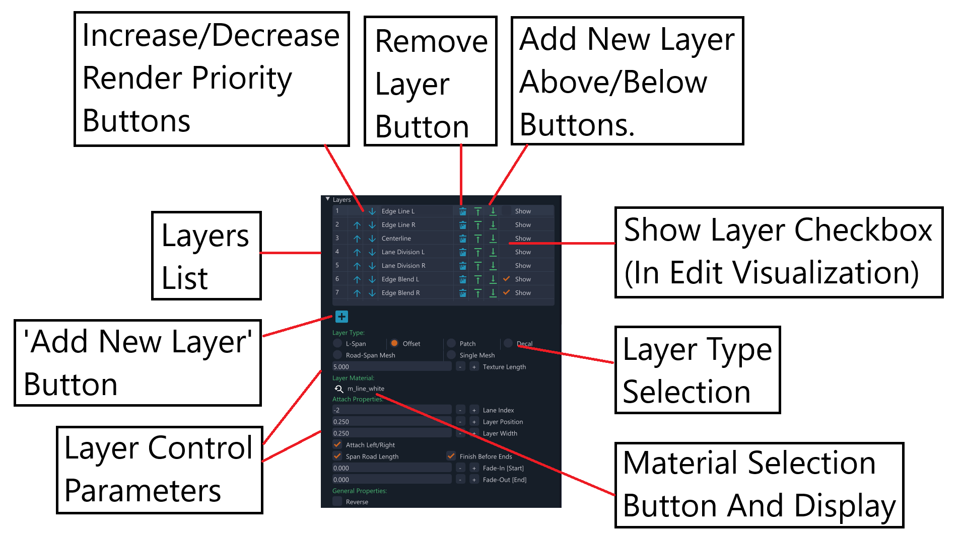
The layers are ordered by priority from top to bottom — the layer at the top of the list has the highest rendering priority (i.e., it will be drawn on top of all others), while the layer at the bottom has the lowest priority. The user can adjust the priority of each layer by moving them up or down the list using the buttons provided in each row (see image above).
New layers can be added using the “Add Layer” button located directly below the Layers List. This will add a new layer to the top of the list, automatically giving it the highest rendering priority. Alternatively, layers can be inserted above or below existing layers using the buttons in each list row (see image above).
In Edit Mode, each layer can be visualized on the road by checking the “Show” checkbox. The selected layer will appear more opaque than others for clarity, while the other visible layers will be more transparent by comparison. This makes it easier to see which layer is selected, if many layers are being shown.
There are six types of layers which can be added, each described below:
L-Span Layers
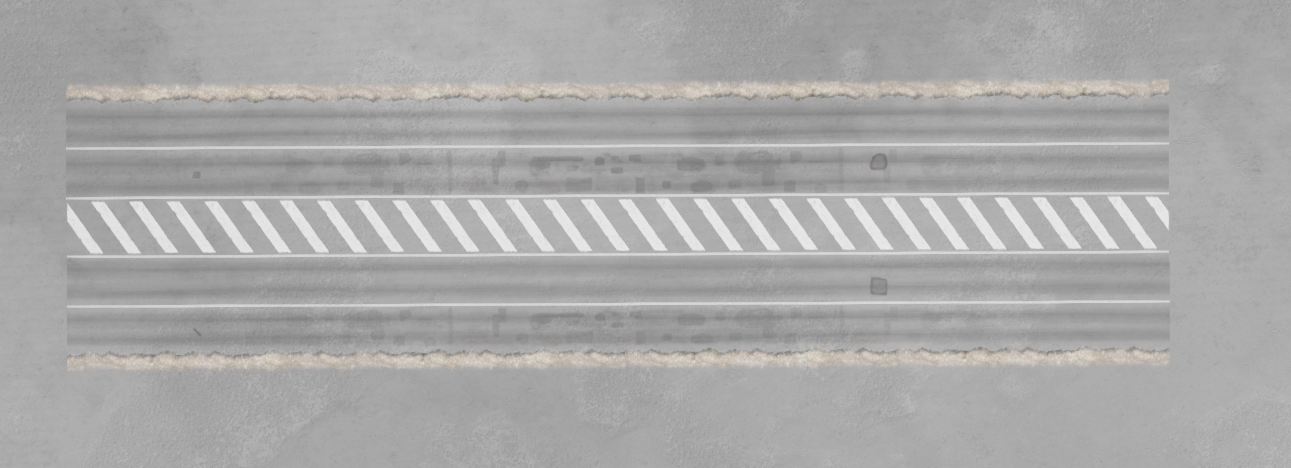
L-Span layers are decal road layers which overlay a longitudinal section of the road (or the full road). They can span one or multiple lanes laterally, which can be set in the properties. These layers adapt to the local width of the lanes they cover at each node and can also be offset laterally. This layer type is useful for various purposes, such as filling a central reservation lane with chevrons or diagonal stripes. An example is shown below.
Control parameters for this layer type include:
Texture Length: Specifies the expected length of the material in meters. This varies for each material and must be supplied by the user, or the default shall be used. If the layer looks stretched, try adjusting this value.
Layer Material: Allows you to select the material from a list. Clicking the button opens the material selection window.
Min Lane Index: Sets the minimum lane index included in the lateral span. Lane indices are marked on the road when the camera is close enough. Note that left lanes have negative indices, and right lanes have positive indices.
Max Lane Index: Sets the maximum lane index included in the lateral span.
Layer Position: Sets the lateral offset of the layer in meters.
Span Road Length: Determines whether the layer spans the entire road length. If unchecked, you can specify start and end nodes.
Finish Before Ends: Controls whether the layer starts and ends slightly inside the road, useful for edge lines that need to stop short of the ends.
Min Node Index: Sets the starting node for the layer (if Span Road Length is not checked).
Max Node Index: Sets the ending node for the layer (if Span Road Length is not checked).
Fade-In [Start]: Sets the amount of fade-in applied at the start of the layer, in meters.
Fade-Out [End]: Sets the amount of fade-out applied at the end of the layer, in meters.
Reverse: Reverses the layer direction, useful for anisotropic materials.
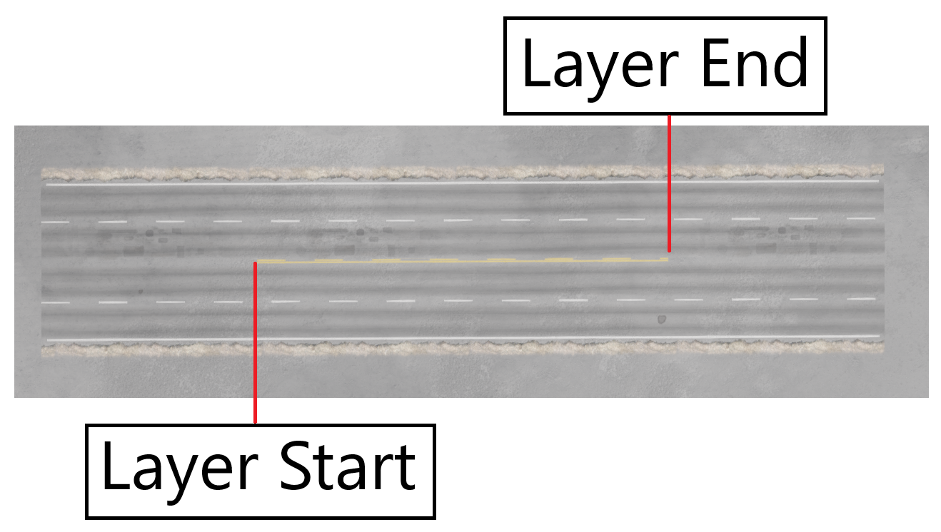
Offset Layers
Offset layers are decal road layers that also overlay a longitudinal section of the road but have a fixed width and are offset from either the left or right side of the lane they are attached to. This layer type is useful for features like road centerlines, edge lines, or lane division lines. An example is shown below.
Control parameters for this layer type include:
Texture Length: Specifies the expected length of the material in meters.
Layer Material: Allows you to select the material from a list.
Lane Index: Sets the lane index to which this layer will be attached.
Layer Position: Sets the lateral offset of the layer in meters.
Layer Width: Sets the lateral width of the layer in meters.
Attach Left/Right: Determines whether the layer is attached to the left or right edge of the lane.
Span Road Length: Determines whether the layer spans the entire road length.
Finish Before Ends: Controls whether the layer starts and ends slightly inside the road.
Min Node Index: Sets the starting node for the layer (if Span Road Length is not checked).
Max Node Index: Sets the ending node for the layer (if Span Road Length is not checked).
Fade-In [Start]: Sets the amount of fade-in applied at the start of the layer, in meters.
Fade-Out [End]: Sets the amount of fade-out applied at the end of the layer, in meters.
Reverse: Reverses the layer direction, useful for anisotropic materials.
Patch Layers
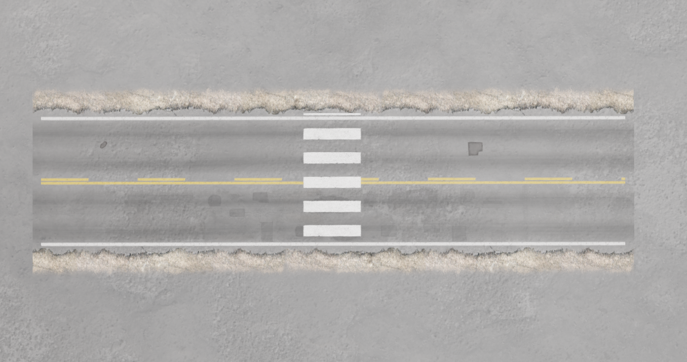
Patch layers are decal road layers that overlay a short longitudinal section of the road, with lateral limits defined by a minimum and maximum lane index. These layers are useful for features like pedestrian crossings or road end paint lines. An example is shown below.
Control parameters for this layer type include:
Texture Length: Specifies the expected length of the material in meters.
Layer Material: Allows you to select the material from a list.
Min Lane Index: Sets the minimum lane index included in the lateral span.
Max Lane Index: Sets the maximum lane index included in the lateral span.
Layer Position: Sets the longitudinal position of the layer, ranging from 0 (road start) to 1 (road end).
Layer Width: Sets the lateral width of the layer in meters.
Decal Layers
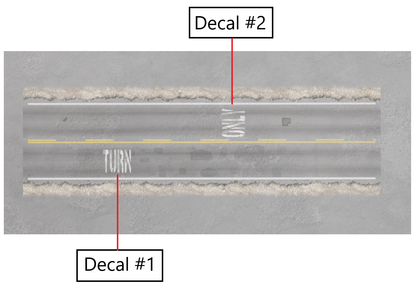
Decal layers are individual decal layers (as opposed to decal road layers) that can be positioned and sized within a patch area in the edit visualization. These layers are useful for adding details like road markings, arrows, or text. An example is shown below.
Control parameters for this layer type include:
Layer Material: Allows you to select the material from a list.
Lane Index: Sets the lane index to which this layer will be attached.
Lateral Offset: Sets the lateral offset from the attached lane, in meters.
Material - Num Rows: Sets the number of rows in the tiled material.
Material - Num Cols: Sets the number of columns in the tiled material.
Frame Number: Sets the frame index for the tiled material.
Decal Size: Sets the size of the rendered decal in meters.
Attach Left/Right: Determines whether the layer is attached to the left or right edge of the lane.
Rotation Around Z-Axis: Sets the rotation around the Z-axis, in degrees, to align the decal.
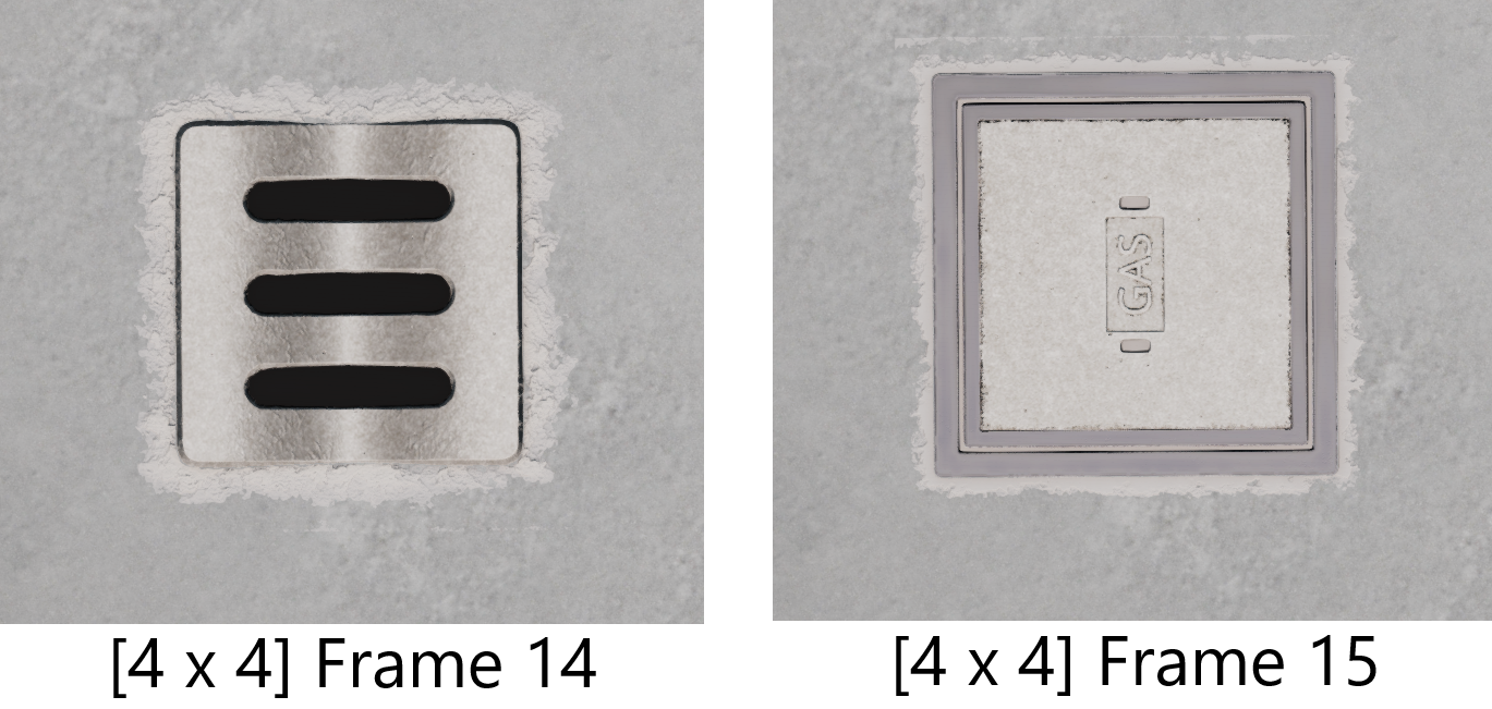
As an example of how the rows, columns, and frame parameters work, consider the ‘ground_parts_decal’ material from the Materials List. If we set this material to have one row and one column (and thus one frame), it will render as shown in the image below.
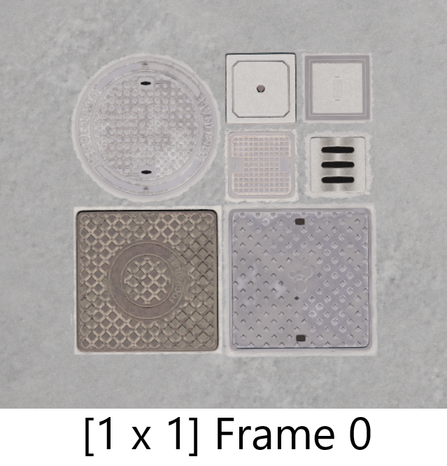
If we instead set the material to have two rows and two columns, we get four frames [0, 1, 2, and 3], which will appear as in the following image.
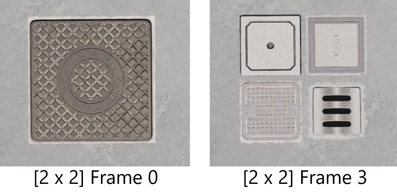
Looking at the original image, we can see that parts of the material are designed to use 2 x 2 tiles, while other parts (the top right quadrant) are designed to use 4 x 4 tiles. If we set the material to have four rows and four columns, we can access those frames individually, as shown in the image below.
Unfortunately, this process is not currently automated or standardized, so users must manually set these parameters when using tile-able decal materials.
Road-Span Mesh Layers
Road-span mesh layers are static mesh layers that overlay a longitudinal section of the road. They consist of a sequence of the same static mesh, spaced by a chosen distance, and can include random jitter for a more natural appearance. These layers are useful for repeating features like lamp posts, crash barriers, or bollards. An example is shown below.
Control parameters for this layer type include:
Static Mesh: Allows you to select the static mesh to be used.
Span Road Length: Determines whether the layer spans the entire road length.
Attach To Left/Right: Determines whether the layer is attached to the left or right edge of the lane.
Min Node Index: Sets the starting node for the layer (if Span Road Length is not checked).
Max Node Index: Sets the ending node for the layer (if Span Road Length is not checked).
Use World Z-Value: Determines whether the static meshes will point directly up (useful for tall objects like lamp posts) or follow the local road incline.
Spacing Between Units: Sets the spacing between each mesh instance in meters. Slightly negative values can be used to seal instances together, such as with barriers.
Lane Index: Sets the lane index to which this layer will be attached.
Lateral Offset: Sets the lateral offset from the attached lane, in meters.
Vertical Offset: Sets the vertical offset from the road surface, in meters.
Amount Of Jitter: Sets the amount of random jitter applied to each instance, adding a worn or lived-in feel to the layer.
Pre-Rotation Around Z-Axis: Sets the rotation around the Z-axis, in degrees, to align the static meshes.
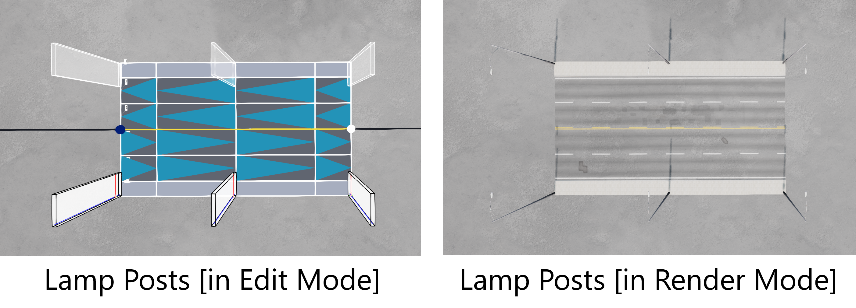
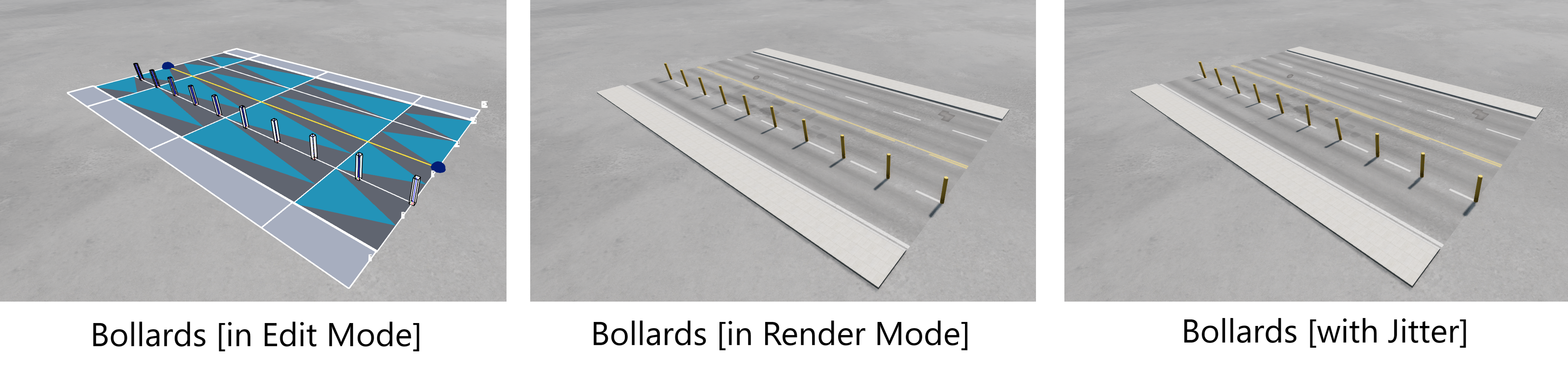
As an example, consider the ‘bollard_yellow’ mesh found in the Mesh Selection List. The sequence of images below shows the bollards placed laterally on a road, both with and without jitter applied.
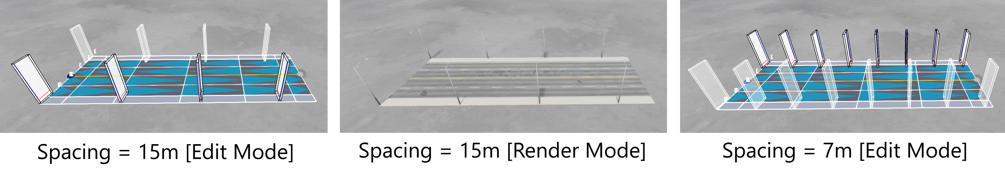
In a second example, consider lamp posts. The first sequence of images demonstrates the effect of adjusting the spacing parameter.
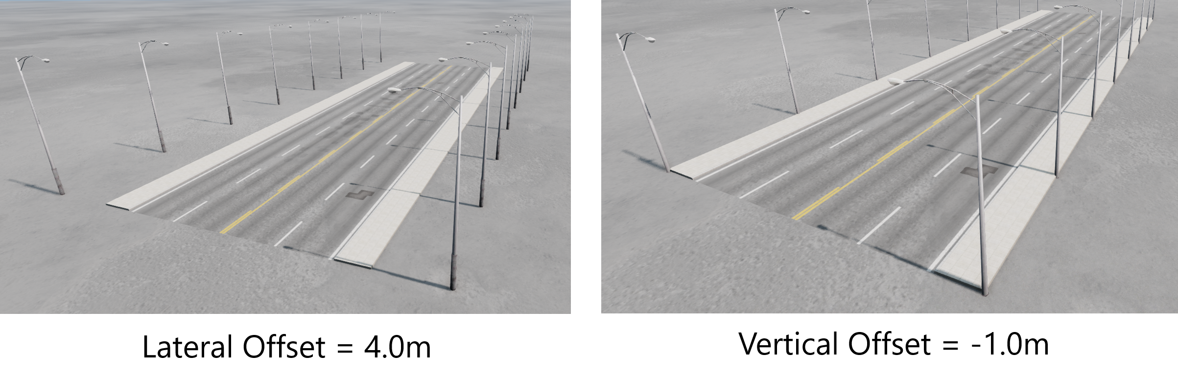
Next, we see the impact of adjusting the lateral and vertical offset parameters.
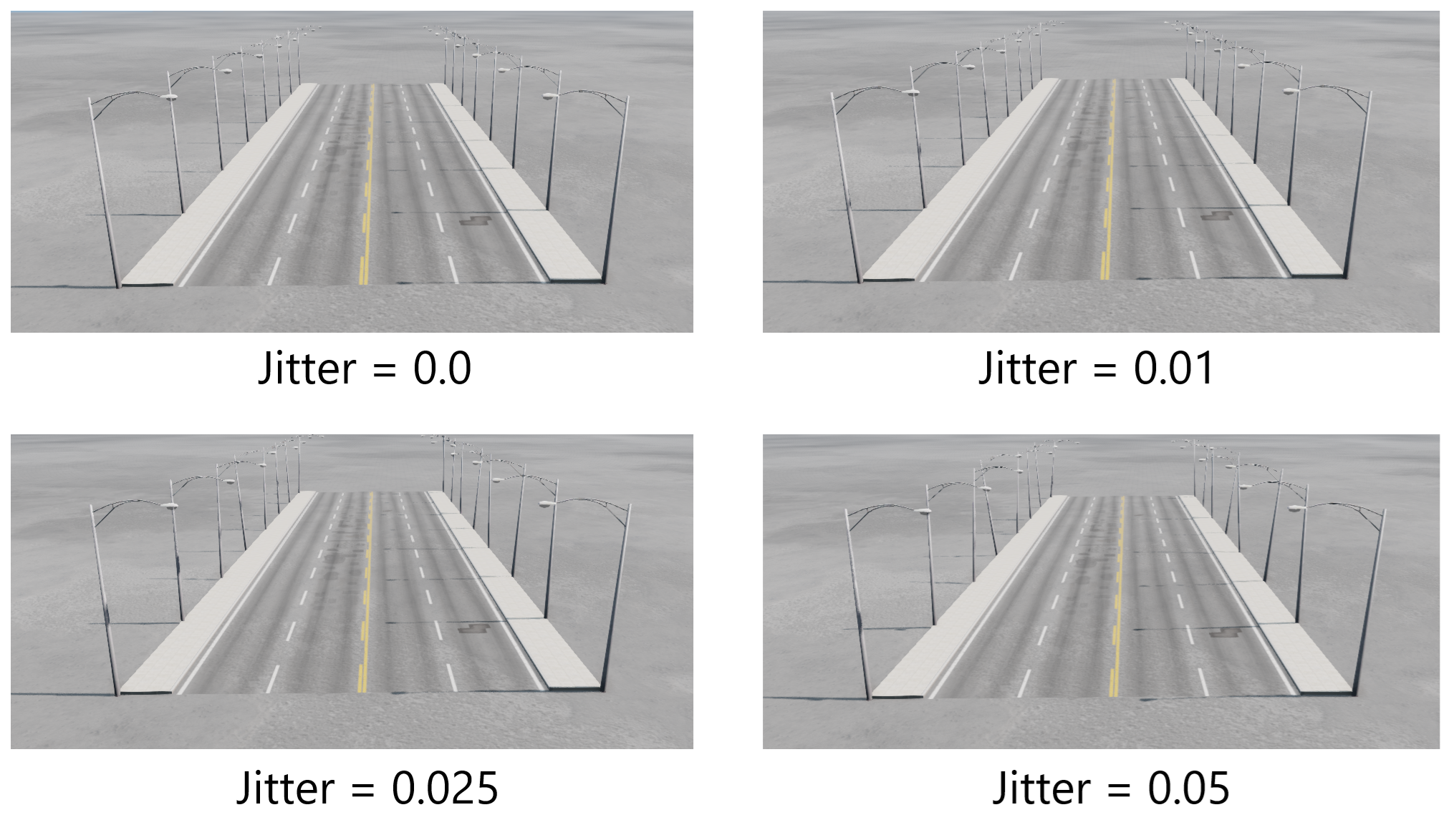
Finally, the last sequence shows the effect of increasing the jitter parameter from zero to an exaggerated amount.
Single Mesh Layers
Single mesh layers consist of a single static mesh instance placed at a specific position on the road. These layers are useful for adding localized details, such as a trash can, oil drum, or a single traffic light pole. An example is shown below.
Control parameters for this layer type include:
Static Mesh: Allows you to select the static mesh to be used.
Lane Index: Sets the lane index to which this layer will be attached.
Attach To Left/Right: Determines whether the layer is attached to the left or right edge of the lane.
Position: Sets the longitudinal position of the layer, ranging from 0 (road start) to 1 (road end).
Lateral Offset: Sets the lateral offset from the attached lane, in meters.
Vertical Offset: Sets the vertical offset from the road surface.
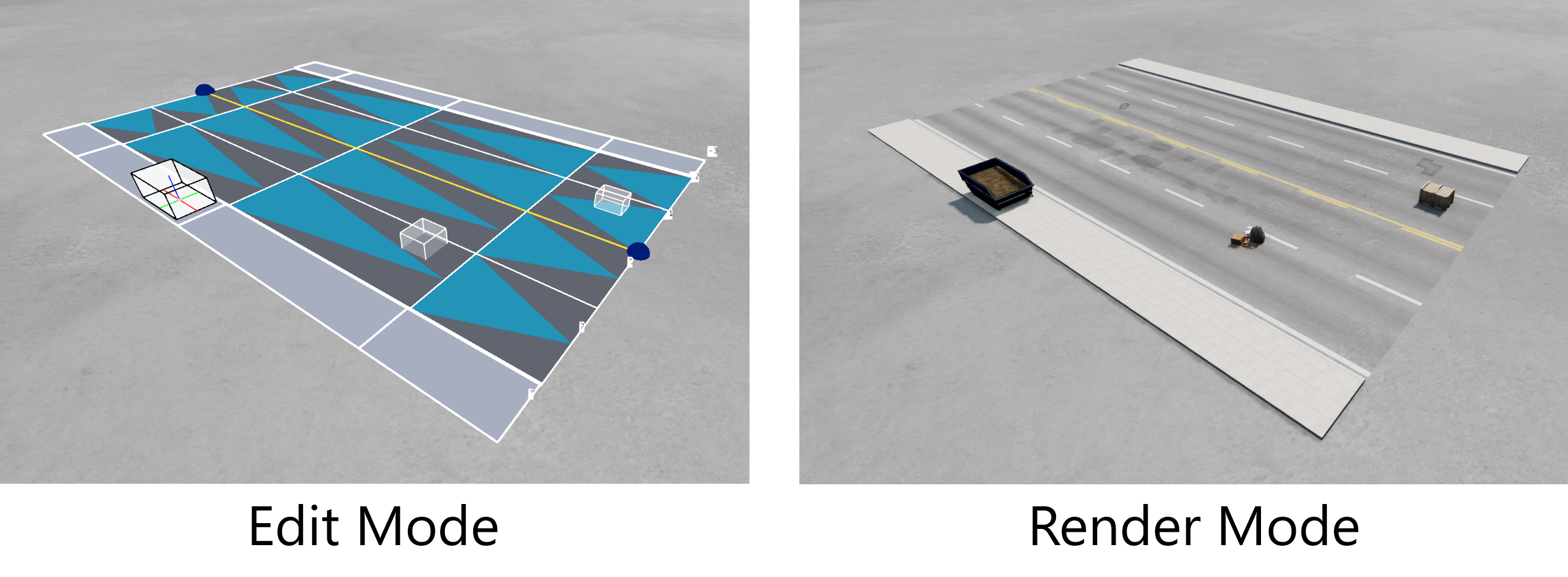
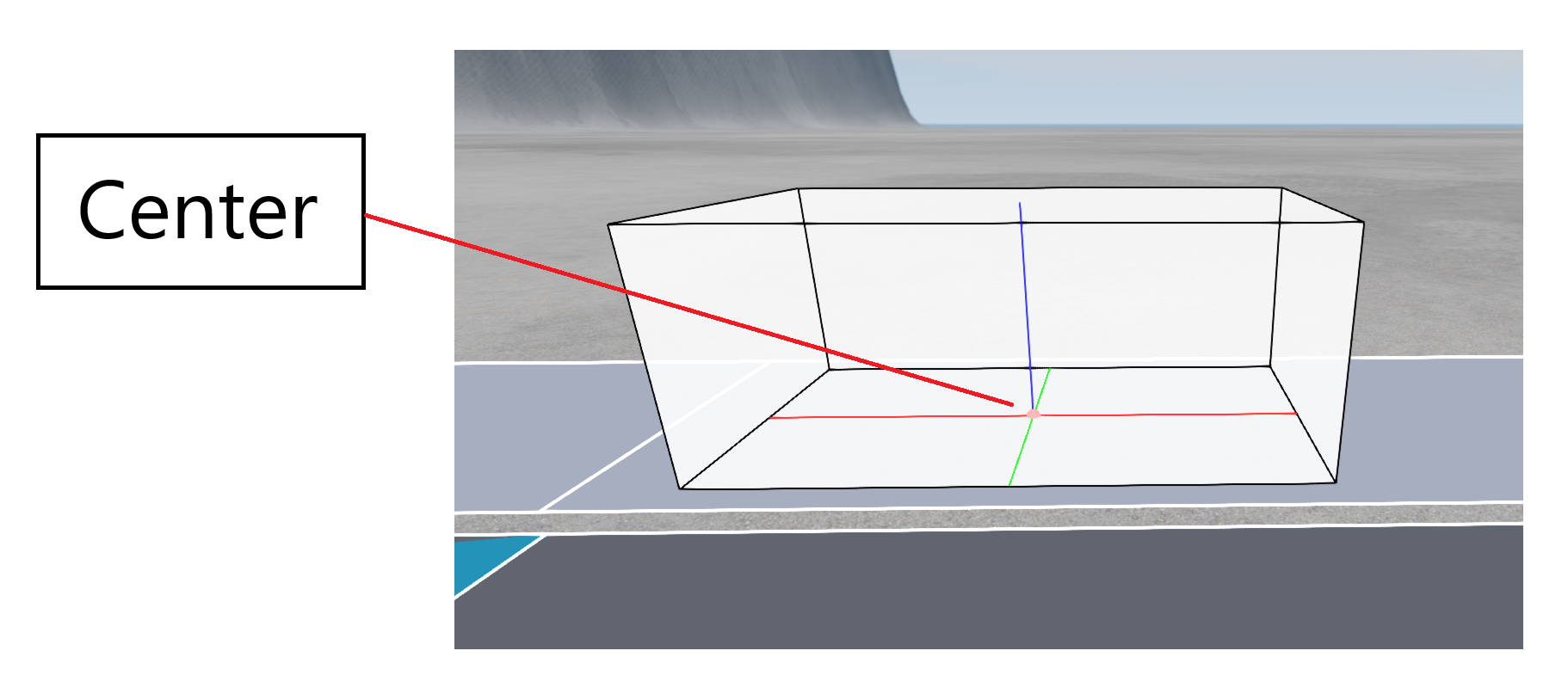
Note: For single mesh layers, as well as Road-Span Mesh Layers, the edit visualization for the selected layer displays each static mesh unit as a bounding box, as illustrated in the image below. The center of each unit is marked for clarity.
Sidewalks
The tool includes a dedicated lane type for sidewalks, which can be used with urban roads. This lane type can be selected in the Profile Edit window and added to any road, typically placed on the left and/or right sides. Sidewalks can also be placed in the center of the road to create a sidewalk ‘island’. For roads with sidewalks, the Sidewalk Controls Section will appear under the Nodes List. This section is illustrated in the image below.
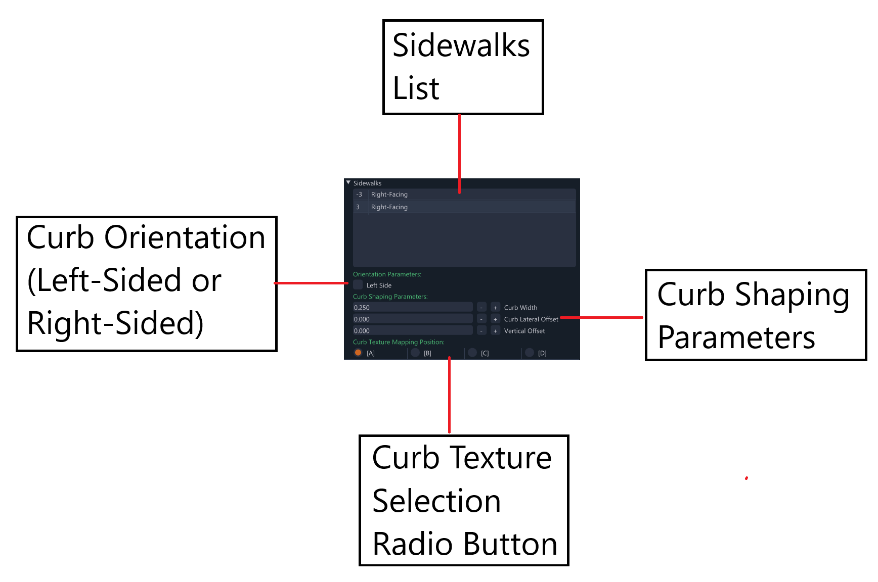
The Sidewalk Controls Section contains parameters for controlling both the sidewalk and curbs for each lane which is designated as a sidewalk. The parameters are described below.
Left Side: A checkbox that indicates whether the curb will appear on the left side of the sidewalk (checked) or the right side (unchecked). Sidewalks on the left side of the road typically have right-facing curbs, and vice versa.
Curb Width: Sets the width of the curb portion of the sidewalk, in meters. Note: This reduces the designated sidewalk space rather than adding extra space - if the curb width is increased, the sidewalk width decreases so that the combined width remains the same as the lane width at each node.
Curb Lateral Offset: Sets a lateral offset for the top corner edge of the curb. This shapes the curb; decreasing the offset tapers the curb inward, while increasing it tapers the curb outward.
Vertical Offset: Sets a vertical offset for the top corner edge of the curb. This also shapes the curb; decreasing the offset lowers the curb as it approaches the outer edge, while increasing it raises the curb as it approaches the outer edge. Experimenting with these curb-shaping parameters can help achieve interesting results for custom sidewalks.
Curb Texture Mapping Position: A radio button that allows the user to select between four distinct UV positions on the special texture used for curbs, each producing different curb textures. Experimenting with these options will help determine what works best for the specific road. We currently only provide one curb material, but in future there should be more choice.
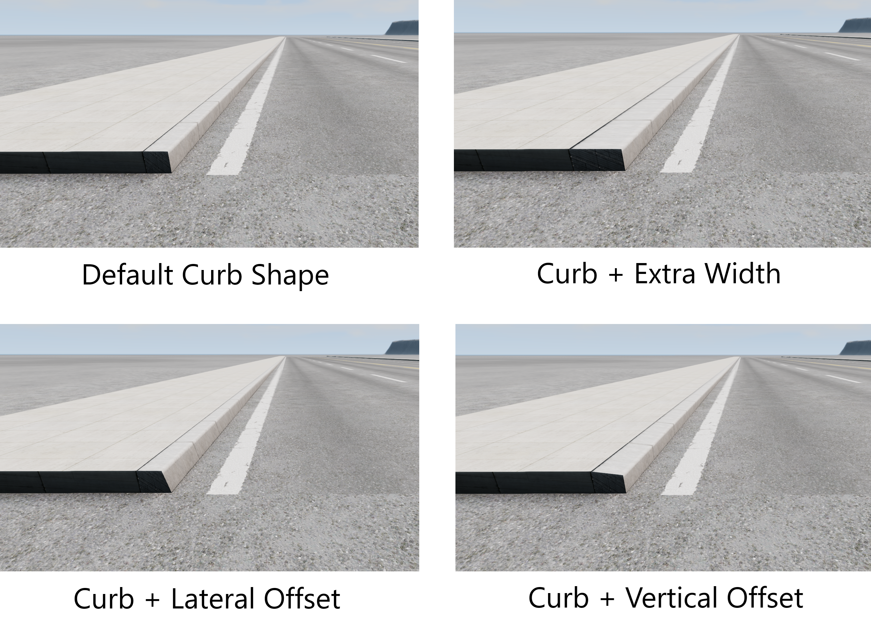
The image below illustrates some curb shaping possibilities using the control parameters described above.
Road Condition Control
The user can control the condition of any road, ranging from clean, new-looking surfaces to dirty, worn roads full of cracks and potholes. This feature provides a fast and convenient way to add detailed wear and tear to the road surface. The parameters for controlling road conditions are found under the Road Condition Control collapsible header under the Nodes List window and are available for any road.
Users can first select the designated class of the road (urban, highway, or dirt). Depending on the selected class, the available options may differ.
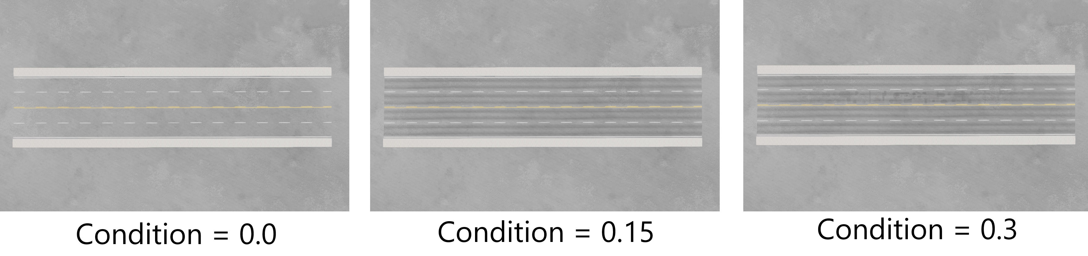
Road Condition: This slider, ranging from 0 to 1, controls the general wear of the road. A value of 0 represents a completely clean road, while 1 represents a very old, dirty road. As the slider increases, a variety of random decal roads are added, including tread marks, repair markings, and cracks. Users should experiment with different values to see what works best for a given road. The following sequence of images shows a road where the condition slider has been set towards the lower end of the range, at various positions.
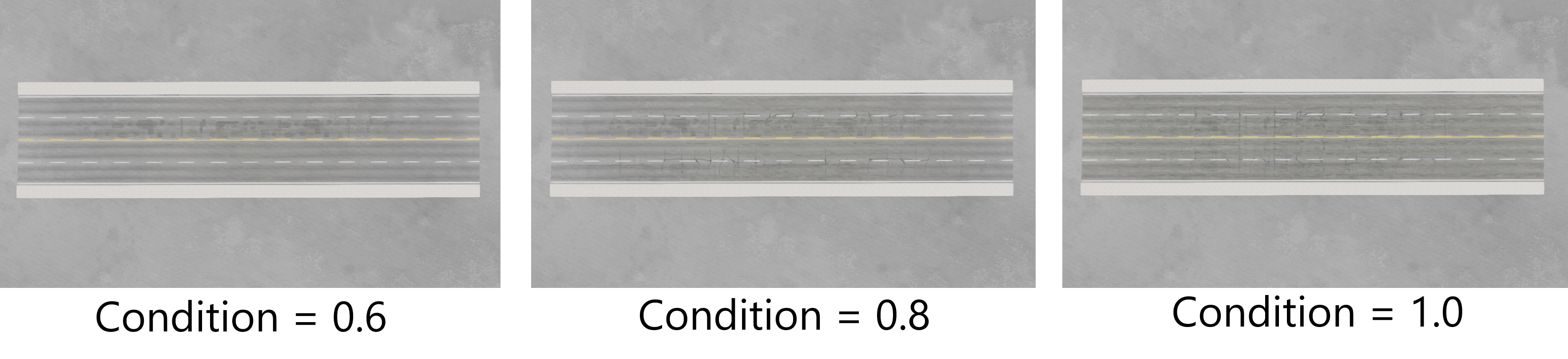
The next image shows the same road, but with larger condition values, approach the highest values in the range. Note the addition of extra cracking texture in the road and general darkening of the surfaces.
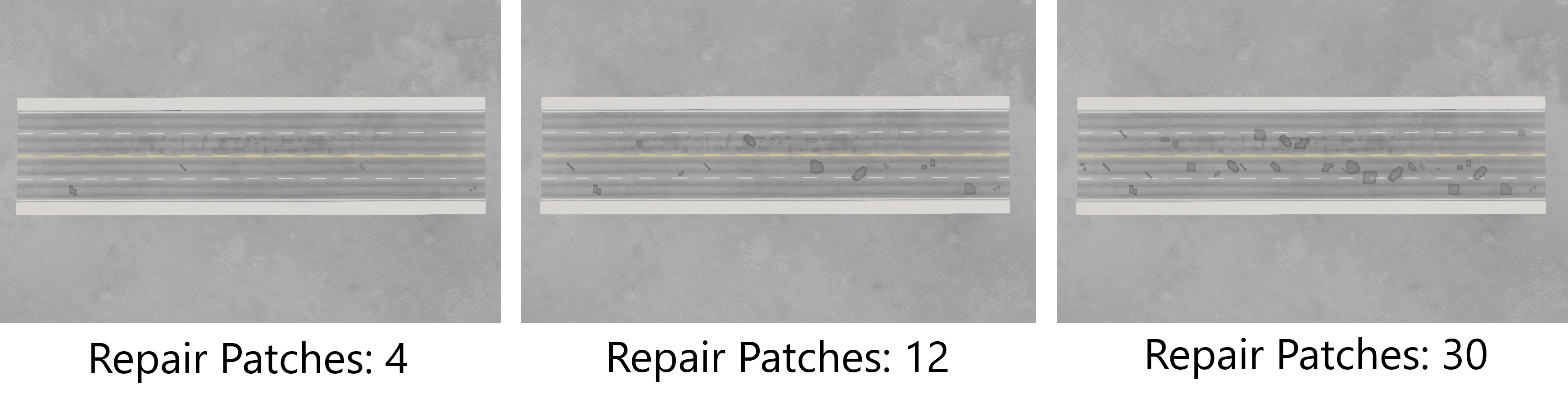
Repair Patches: This parameter sets the number of repair patches (special decals) that appear on the road. These patches are distributed randomly across the surface. The following sequence of images show a road with a varying number of repair patches, using the same random seed value.
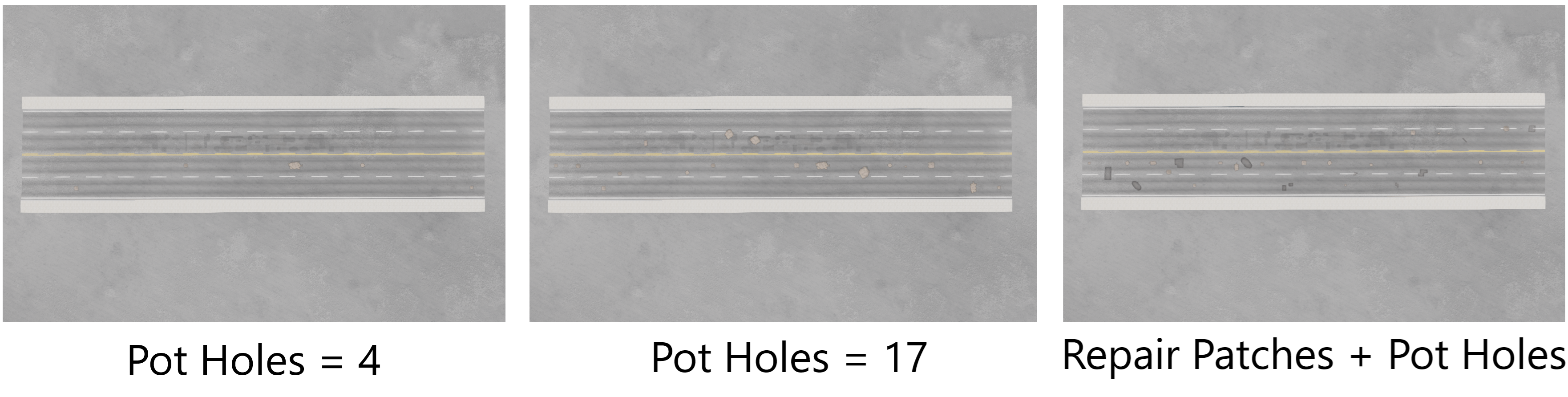
Potholes: This parameter sets the number of potholes (special decals) that appear on the road, also distributed randomly. The following sequence of images show a road with a varying number of potholes, using the same random same value. The rightmost image shows the effect of having both repair patches and pot holes at the same time, providing some added variety.
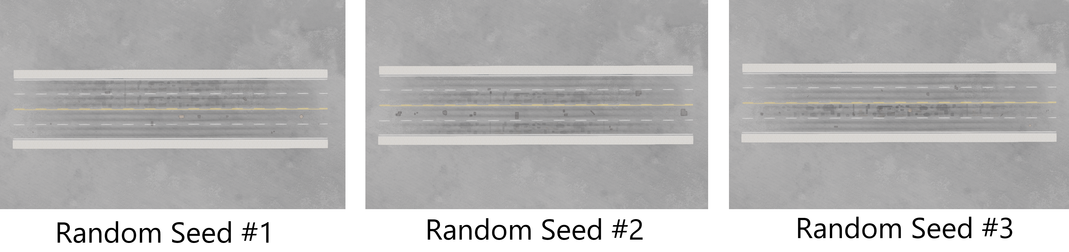
Random Seed Value: This controls the seed used for randomization when generating the road condition. Changing the seed will alter the placement of wear marks, cracks, repair patches, and potholes. Experimenting with this value is recommended, as some seeds may create a more natural appearance than others. The following sequence of images shows a road containing some repair patches, pot holes, and conditioning, and how these change with various random seed values.
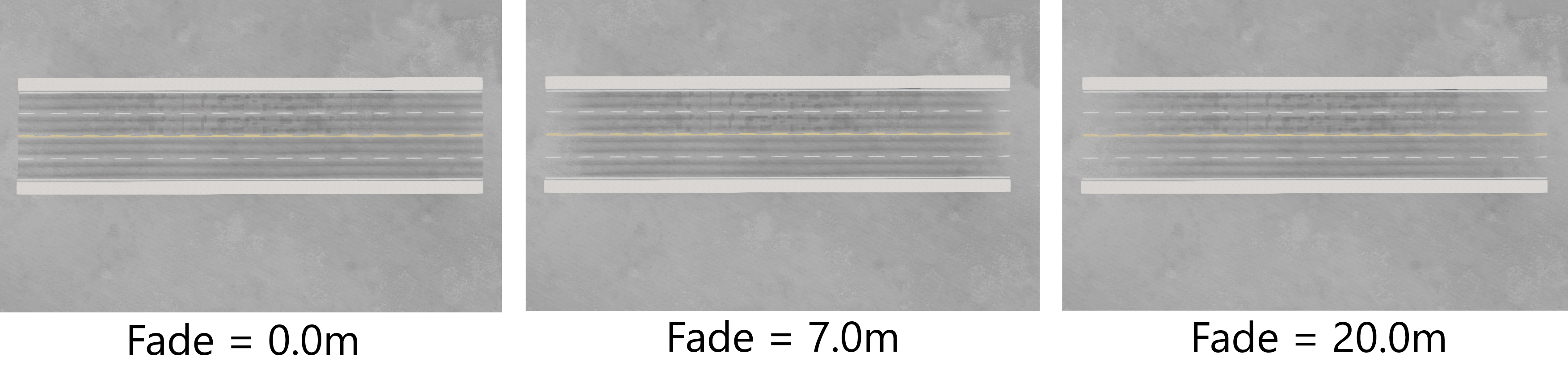
Fade-In [Start]: This parameter sets the fade-in distance at the start of the road, in meters, where the conditioning begins to take effect.
Fade-Out [End]: This parameter sets the fade-out distance at the end of the road, in meters, where the conditioning stops taking effect.
The following sequence of images show a road with various fading values.
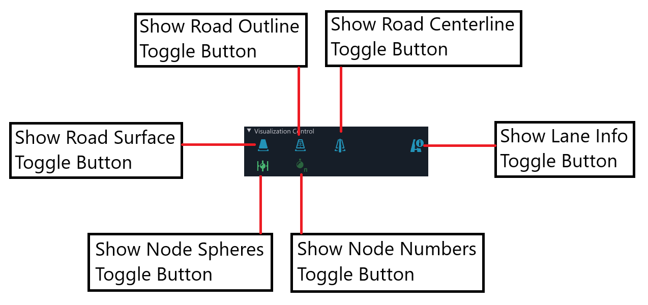
Visualization Control
The Visualization Control collapsible header, located beneath the Nodes List, contains two rows of buttons that toggle various aspects of the edit visualization on or off. The image below illustrates the available visualization control toggle buttons.
Was this article helpful?